Sodium management for dialysis systems
A technology of dialysate and sodium ions, applied in the field of dialysis therapy, can solve the problems of high cost of adsorbent, change of sodium level, difficulty in verifying purity, etc.
- Summary
- Abstract
- Description
- Claims
- Application Information
AI Technical Summary
Problems solved by technology
Method used
Image
Examples
example 1
[0088] Example 1: ZrP ion exchange column in acidic form
[0089] The ion exchange column in acidic form was prepared by filling an empty chromatographic column (GE C10 / 10 column: 19-5001 -01), and wash with 500mL0.1M hydrochloric acid solution at 5mL / min to ensure that the cation exchange column is in acidic form. The column was flushed with 500 mL of deionized ("DI") water at 5 mL / min to ensure that residual hydrochloric acid in the column was removed prior to the experiment.
[0090] The exemplary solution was used in the experiment and the flow rate was measured at 5.88 mL / min. Samples were collected at the outlet of the column every five minutes, and time zero was defined when the exemplary solution completely replaced the DI water initially in the column. All samples were analyzed by clinical chemistry methods to measure ion concentrations. result( Figure 5 ) shows that at elution volumes between 104 and 310 mL, the sodium concentration reaches a plateau at about ...
example 2
[0091] Example 2: ZrP ion exchange column in sodium form
[0092] A column in the sodium form was prepared in a similar manner by successively filling an empty column with 3.622 g of zirconium phosphate resin and 1.984 g of activated carbon (CR2050C-AW, lot number CA10-2 from Carbon Resources) and filling it with 500 mL of saturated sodium bicarbonate solution was flushed at 5 mL / min to ensure that the cation exchange column was in the sodium form. The column was flushed with 500 mL DI water at 5 mL / min to ensure that residual sodium bicarbonate in the column was removed prior to the experiment.
[0093]The exemplary solution was used in the experiment and the flow rate was measured to be 4.3 mL / min. Samples were collected at the outlet of the column every five minutes, and time zero was defined when the exemplary solution completely replaced the DI water initially in the column. All samples were analyzed by clinical chemistry methods to measure ion concentrations. result...
example 3
[0094] Example 3: Combined ZrP column in acidic and sodium form
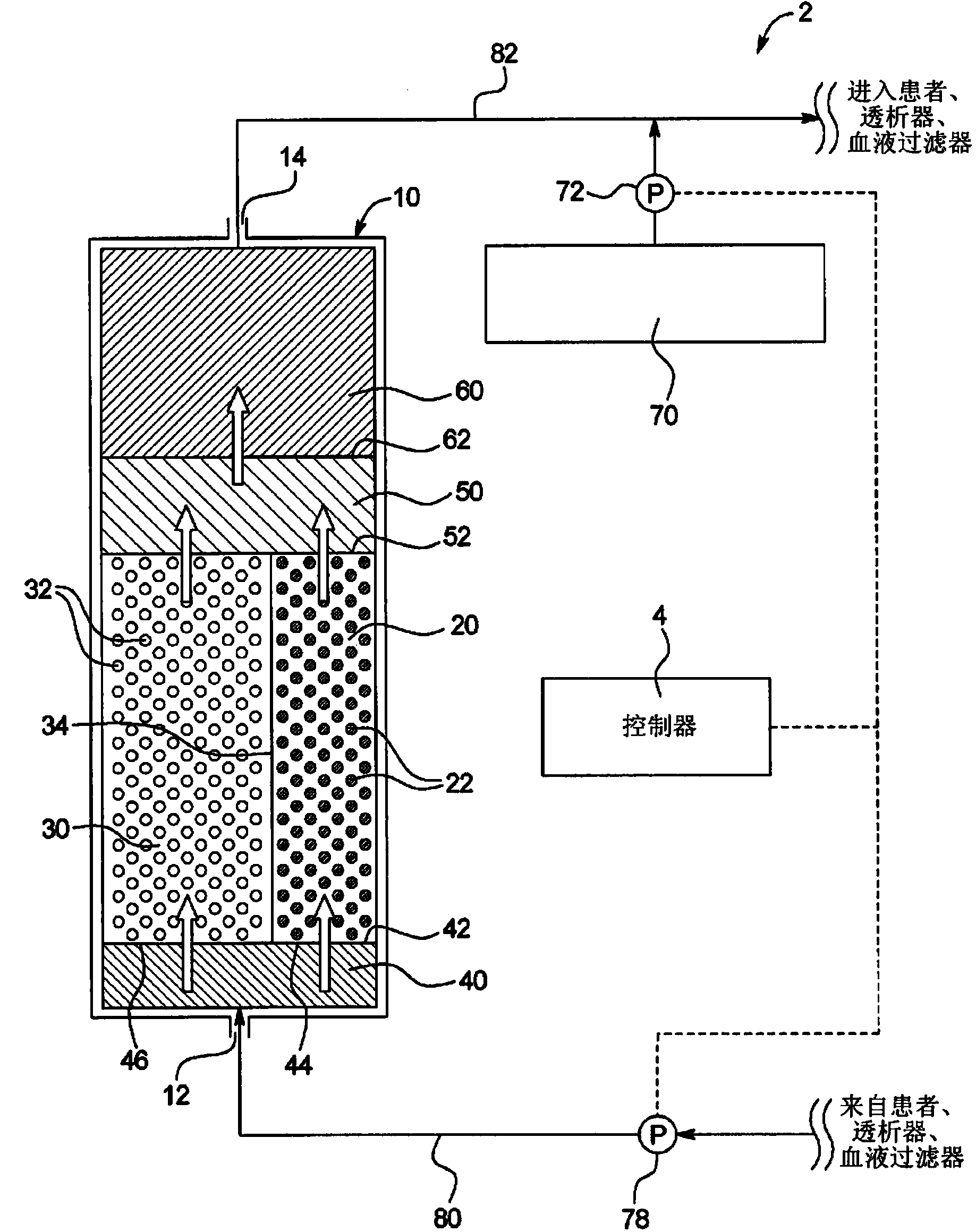
[0095] Based on the results from the two separate columns, a volumetric flow rate ratio modification of 3:1 was made to balance the output sodium levels through the combined parallel columns. The same column was used in this experiment. The flow rate through this column in the acid form was measured to be 1.61 mL / min and the flow rate through the column in the sodium form was measured to be 4.85 mL / min. The flows from the two columns are combined into one flow through a Y-connector with mixing capability. Samples were collected every four minutes and time zero was defined when the exemplary solution completely replaced the DI water initially in the column. All cations and anions were analyzed by clinical chemistry methods and pH was measured. Figure 7 Representative of typical results showing that the sodium concentration remains relatively constant at about 140 mM at elution volumes between 101 and 230 mL...
PUM
 Abstract
Description
Claims
Application Information
 - R&D
- Intellectual Property
- Life Sciences
- Materials
- Tech Scout
- Unparalleled Data Quality
- Higher Quality Content
- 60% Fewer Hallucinations
Browse by: Latest US Patents, China's latest patents, Technical Efficacy Thesaurus, Application Domain, Technology Topic, Popular Technical Reports.
© 2025 PatSnap. All rights reserved.Legal|Privacy policy|Modern Slavery Act Transparency Statement|Sitemap|About US| Contact US: help@patsnap.com


