Exhaust gas treatment device, method for processing exhaust gas, and motor vehicle

A technology for exhaust gas treatment device and motor vehicle, which is applied in the direction of exhaust device, exhaust gas treatment, muffler device, etc., can solve problems such as inability to convert, and achieve the effect of reducing CO2 emission and having a simple structure

Active Publication Date: 2014-04-23
VOLKSWAGEN AG
View PDF8 Cites 4 Cited by
  • Summary
  • Abstract
  • Description
  • Claims
  • Application Information

AI Technical Summary

Problems solved by technology

This means that the combustion engine cannot optimally convert the chemical energy of the propellant into the kinetic energy of the motor vehicle
Furthermore, protracted combustion by propellant can only be achieved in reduction catalysts at approximately 400°C to 450°C

Method used


Image

  • Exhaust gas treatment device, method for processing exhaust gas, and motor vehicle
  • Exhaust gas treatment device, method for processing exhaust gas, and motor vehicle
  • Exhaust gas treatment device, method for processing exhaust gas, and motor vehicle

Examples


Embodiment Construction

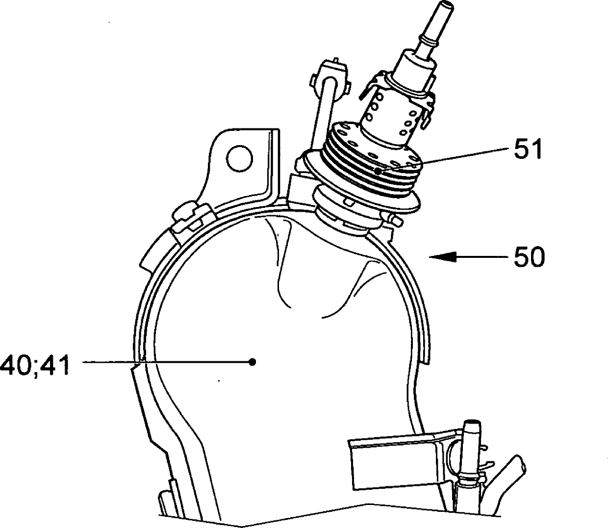
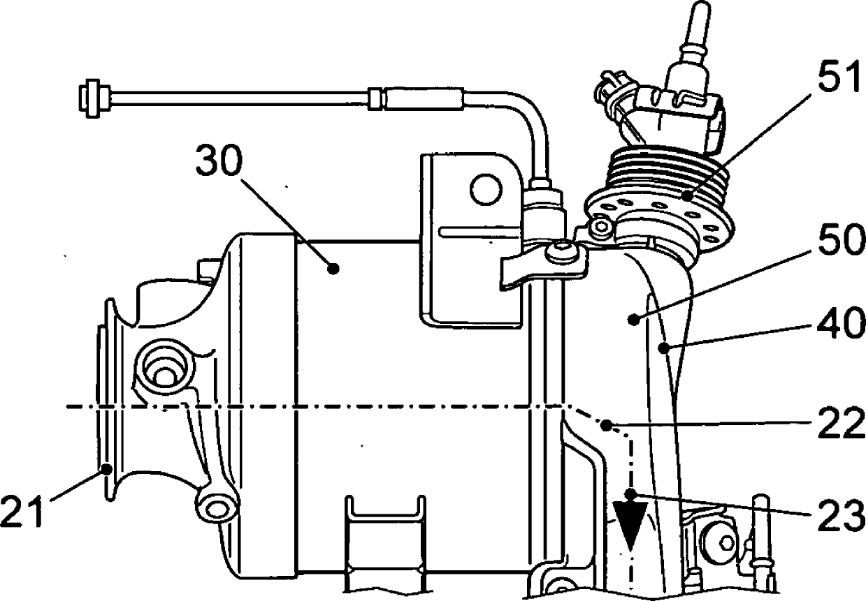
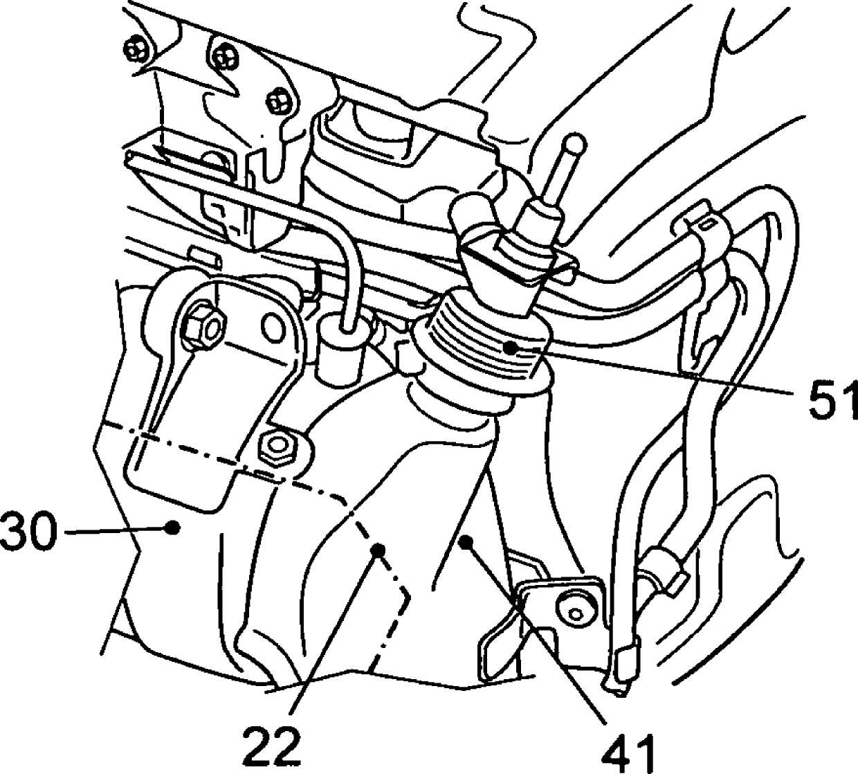
[0037] exist figure 1 A combustion device 10 can clearly be seen in the figure, on the exhaust system 20 of which the oxidation catalyst 30 is arranged on the connecting device 21, and downstream in the exhaust gas flow direction 23 in the exhaust gas system 20 shown in dotted lines The reduction catalytic converter 50 is arranged in the gas line 22 on the connecting module 40 or its housing 41 . The connecting module 40 leads to a particle filter 60 which is likewise arranged in the exhaust gas line 22 .

[0038] That is to say that reduction catalytic converter 50 is arranged on housing 41 of connecting module 40 between oxidation catalytic converter 30 and particle filter 60 .

[0039] In contrast to conventional embodiments, the reduction catalytic converter 50 is thus arranged in a very tight manner on the combustion system 10 or on the connecting device 21 so that the exhaust gas heat produced by the exothermic reaction in the combustion system 10 is used to convert Th...


PUM


Abstract

The invention relates to an exhaust gas treatment device for processing exhaust gas from a combustion unit, in particular a diesel engine. Furthermore, the invention relates to a method for processing exhaust gas from a combustion unit by selective catalytic reaction, and to a motor vehicle, in which the method according to the invention is implemented or which includes the exhaust gas treatment device according to the invention. According to the invention, the exhaust gas treatment device comprises an exhaust gas system and an oxidation catalyst, a reduction catalyst for selective catalytic reduction and a particle filter arranged therein, wherein the oxidation catalyst is arranged upstream of the reduction catalyst and the reduction catalyst is arranged upstream of the particle filter. The reduction catalyst (50) is arranged in the exhaust gas system (20) so far upstream in the exhaust gas flow direction (23) that the heat of the exhaust gas passing through the reduction catalyst (50) is sufficient to bring the reduction catalyst (50) to operating temperature.

Description

technical field [0001] The invention relates to an exhaust gas treatment device for treating the exhaust gas of a combustion system, in particular a diesel engine. The invention also relates to a method for treating exhaust gases of combustion plants by selective catalytic reactions and to a motor vehicle in which the method according to the invention is carried out or has exhaust gas treatment according to the invention device. Background technique [0002] Thorough and effective cleaning of combustion engine exhaust can be achieved by adding a reducing agent to the exhaust in an exhaust aftertreatment device. In this case, nitrogen oxides are reduced in the exhaust gas in particular in lean-operated combustion engines in which an excess of air relative to the stoichiometric fuel-air mixture is present for combustion. Conventional ammonia is used as a reagent. Nitrogen oxides are reduced together with ammonia to harmless components such as water and nitrogen at sufficien...

Claims


Application Information

Patent Timeline
Patent Type & Authority Applications(China)
IPC IPC(8): F01N13/02F01N3/20
CPCY02T10/24F01N2610/02F02M25/0735F01N3/10F01N2340/02F01N13/009Y02T10/121F01N3/2066F01N3/106F02M25/0709F01N3/035F01N2610/11F02M25/0718F01N13/0097F01N2610/1453F02M26/06F02M26/15F02M26/30Y02A50/20Y02T10/12
Inventor J.施普鲁特
Owner VOLKSWAGEN AG
Why Eureka
Try Eureka