Iodine pentafluoride production equipment and production method

A technology of iodine pentafluoride and production equipment, applied in the direction of inter-halogen compounds, etc., can solve the problems of easy formation of agglomerates of iodine, low iodine solubility, and inability to continuously perform production, and achieves good cooling and condensation effects and heat exchange efficiency. High and full use of energy

Active Publication Date: 2014-04-30
FUJIAN YONGJING TECH CO LTD
View PDF2 Cites 3 Cited by
  • Summary
  • Abstract
  • Description
  • Claims
  • Application Information

AI Technical Summary

Problems solved by technology

[0015] 1. The solubility of iodine in iodine pentafluoride liquid is low, and undissolved iodine is easy to form agglomerates in iodine pentafluoride liquid. After the fluorine gas is introduced, the contact area with iodine is too small, and the reaction rate is very low. A large amount of unreacted fluorine gas will cause environmental pollution and safety problems
[0016] 2. Due to the low solubility of iodine in iodine pentafluoride liquid, the amount of iodine added is small, that is, frequent iodine addition is required, and the production cannot be carried out continuously
It is necessary to stop the input of fluorine gas when extracting the miscellaneous gas from the reactor, and only intermittent production can be used
[0017] 3. The reaction is carried out under negative pressure. As the reaction temperature rises, a large amount of iodine pentafluoride volatilizes into gas, and is discharged from the reactor when the negative pressure is pumped for the second time, and the reaction yield is low.
[0018] 4. The reaction is carried out under the negative pressure of -0.06~-0.08Mpa, which requires high sealing of the reactor. If the sealing is not good, it is easy to inhale air, especially humid air, which will cause the combustion of fluorine gas and pentafluorine in the reactor. Iodine decomposition reaction produces iodic acid and hydrofluoric acid, which affects the quality

Method used


Image

  • Iodine pentafluoride production equipment and production method

Examples


Embodiment Construction

[0050] In order to describe the technical content, structural features, achieved goals and effects of the present invention in detail, the following will be described in detail in conjunction with the embodiments and accompanying drawings.

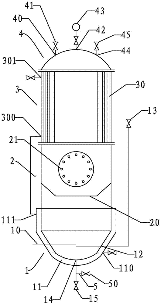
[0051] see figure 1As shown, the iodine pentafluoride production equipment of the present embodiment includes a closed reactor, and the reactor includes a liquid phase zone 1, a solid phase zone 2, a condensation zone 3 and an exhaust zone 4 from bottom to top; A temperature measuring rod 10 is arranged in the liquid phase area 1, and a cooling water jacket 11 is arranged outside the liquid phase area 1, and the water inlet 110 of the cooling water jacket 11 is located at the bottom of the cooling water jacket 11, so The water outlet 111 of the cooling water jacket 11 is located at the top of the cooling water jacket 11, and the side of the liquid phase region 1 is provided with a fluorine gas inlet 12, and the fluorine gas inlet 12 is con...


PUM

PropertyMeasurementUnit
melting pointaaaaaaaaaa
boiling pointaaaaaaaaaa

Abstract

The invention discloses an iodine pentafluoride production method characterized by continuous reaction, high yield, mild and complete reaction, and extremely light pollution degree. The method includes: in an airtight reactor, placing solid iodine above liquid iodine pentafluoride or an iodine pentafluoride solution of iodine; then introducing fluorine gas into the liquid iodine pentafluoride or the iodine pentafluoride solution of iodine, and simultaneously employing a flowable cooling medium to cool the liquid iodine pentafluoride or the iodine pentafluoride solution of iodine and the gas phase generated above solid iodine in a flow direction from the bottom up, controlling the temperature of the liquid iodine pentafluoride or the iodine pentafluoride solution of iodine at 15-100DEG C, and making the iodine pentafluoride steam and iodine steam in the gas phase generated above the solid iodine condense and flow back to the liquid iodine pentafluoride or the iodine pentafluoride solution of iodine. The invention also discloses production equipment special for the method.

Description

technical field [0001] The invention relates to a production equipment and production method of iodine pentafluoride. Background technique [0002] Iodine pentafluoride is often used as a fluorinating agent, fire starter, and oil and water repellent of textiles. Iodine pentafluoride is a liquid with a density of 3.23g / mL, a melting point of 9.4°C and a boiling point of 104.5°C. [0003] The main way to produce iodine pentafluoride is to prepare iodine pentafluoride by reacting iodine and fluorine gas. At normal temperature and pressure, iodine is a solid with a density of 4.21g / mL and can be dissolved in iodine pentafluoride. Fluorine gas is a gas, and fluorine is a strong oxidizing agent and the most active element. Fluorine gas has a strong pungent odor and is highly toxic. The currently prevailing preparation method is that iodine is burned in fluorine gas and fluorine gas is passed into the iodine pentafluoride liquid in which part of the iodine has been dissolved: ...

Claims


Application Information

Patent Timeline
Patent Type & Authority Applications(China)
IPC IPC(8): C01B7/24
Inventor 谢国辉罗建文
Owner FUJIAN YONGJING TECH CO LTD
Why Eureka
Try Eureka