Mechanical combustion biomass boiler

A biomass boiler and boiler technology, applied in the field of boilers, can solve the problems of restricting the application and development of biomass gasification technology, the boiler cannot be operated and used, and the thermal efficiency is low, so as to avoid corrosion problems, low cost, and improve thermal efficiency.

Inactive Publication Date: 2014-04-30
孙长杰
View PDF0 Cites 0 Cited by
  • Summary
  • Abstract
  • Description
  • Claims
  • Application Information

AI Technical Summary

Problems solved by technology

[0002] At present, with the massive consumption of non-renewable energy such as coal, oil, and natural gas, the shortage is increasing, and the use of traditional combustion methods will also cause environmental pollution. As a renewable energy source, biomass materials are receiving more and more attention from the society, but , the current biomass gasification technology only stays in the use of gasifiers to produce combustible gas for daily cooking, which greatly limits the application and development of biomass gasification technology
At present, environmentally friendly boilers burning renewable energy granular biomass are being widely promoted and applied at home and abroad, but the existing biomass boilers still have problems such as insufficient combustion, large smoke, not environmentally friendly, low thermal efficiency, and inconvenient maintenance. Especially in the combustion process, because the biomass boiler contains a lot of chlorine and alkaline substances, the fly ash particles of these substances are bonded to the boiler body, causing serious corrosion of the boiler, which makes the boiler unable to operate within a heating period use

Method used


Image

  • Mechanical combustion biomass boiler
  • Mechanical combustion biomass boiler

Examples


Embodiment Construction

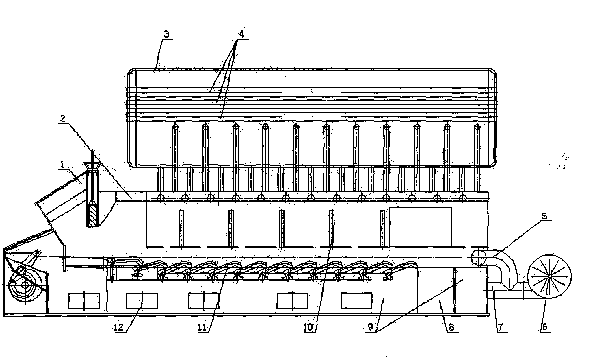
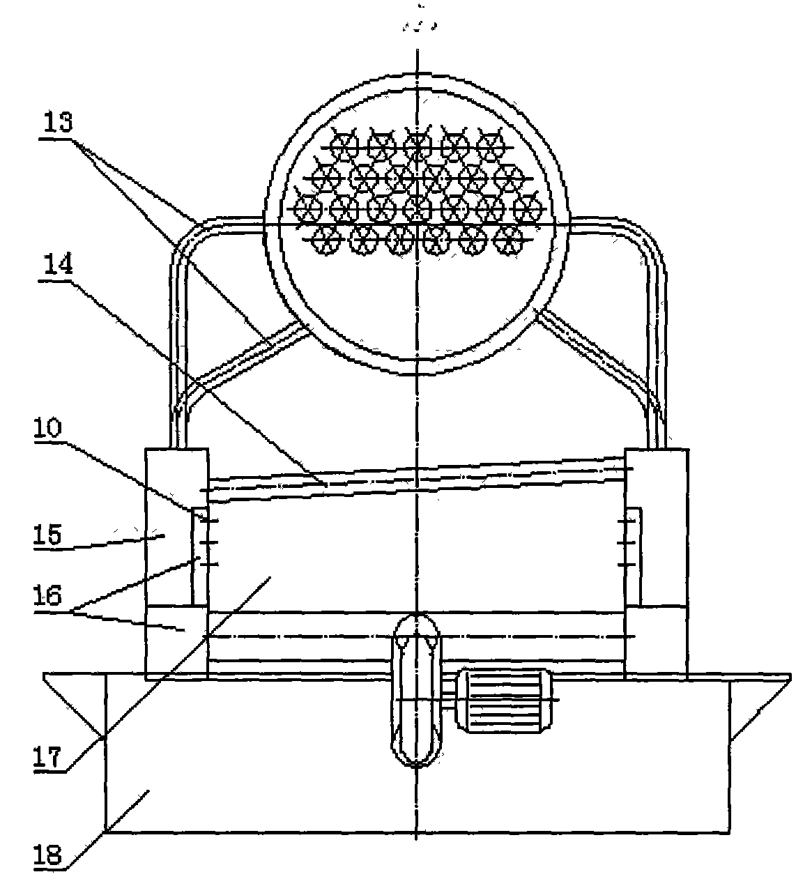
[0013] A mechanically fired biomass boiler includes a boiler body, a base 18, an automatic feeding device 1, a reciprocating fire grate 11, a drum 3 and water-cooled wall tubes 13. The main body of the boiler is composed of left and right water boxes 15, left and right secondary air boxes 16, and upper arched horizontal water pipes 14. The base 18 is provided with an air chamber 9, a slag removal port 8 and a damper 12; The upper top is provided with a fire outlet 2, and the front of the furnace is equipped with an automatic feeding device 1; the left and right water boxes 15 are drilled with multiple secondary air inlet holes 10 on the steel plate on the side of the furnace, and the inside and bottom of the left and right water boxes 15 are arranged with two The secondary air box 16; the main body of the boiler is welded on the base 18, the main body of the boiler is located at the bottom of the furnace, and a reciprocating fire grate 11 is installed, and the rear end of the a...


PUM


Abstract

A mechanical combustion biomass boiler comprises a boiler body, a base and a boiler barrel. The boiler body is composed of a left water box, a right water box, a left secondary wind box, a right secondary wind box and an upwarping transverse water pipe. A hearth is arranged in the middle of the boiler body. An automatic feed device is arranged on the front portion of the hearth. Multi-point secondary air inlets are drilled in steel plates on the sides, close to the hearth, of the left water box and the right water box. The secondary wind boxes are arranged inside and on the bottom portions of the left water box and the right water box. The boiler body is welded to the base. A reciprocating grate is arranged on the portion, located at the bottom of the hearth, of the boiler body. An air inlet is formed in the portion, at the rear ends of the wind boxes, at the bottom of the hearth. The air inlet is connected with one end of a secondary air pipe, and the other end of the secondary air pipe is connected and communicated with a primary air pipe. One end of the primary air pipe is connected with an air blower, and the other end of the primary air pipe is communicated with an air chamber. A smoke and fire pipe bundle is arranged inside the boiler barrel, the boiler barrel is erected on the boiler body, and the boiler barrel is connected and communicated with the water boxes on the boiler body through water wall pipes. The mechanical combustion biomass boiler has the advantages of being sufficient in combustion, low in cost, capable of saving energy, environmentally friendly, long in service life and the like.

Description

technical field [0001] The invention relates to a boiler, in particular to a boiler for mechanically burning biomass. Background technique [0002] At present, with the massive consumption of non-renewable energy such as coal, oil, and natural gas, the shortage is increasing, and the use of traditional combustion methods will also cause environmental pollution. As a renewable energy source, biomass materials are receiving more and more attention from the society, but At present, biomass gasification technology only stays in the use of gasifier to produce combustible gas for daily cooking, which greatly limits the application and development of biomass gasification technology. At present, environmentally friendly boilers burning renewable energy granular biomass are being widely promoted and applied at home and abroad, but the existing biomass boilers still have problems such as insufficient combustion, large smoke, not environmentally friendly, low thermal efficiency, and in...

Claims


Application Information

Patent Timeline
Patent Type & Authority Applications(China)
IPC IPC(8): F23B30/10F24H1/44
Inventor 孙长杰
Owner 孙长杰
Why Eureka
Try Eureka