Glow discharge-based plasma generator and spectrum detection system formed by same

A generation device and plasma technology, applied in the field of analytical chemical spectrum analysis, can solve the problems of reduced sensitivity, weakened detection signal, short service life, etc., and achieve the effect of reducing interference and enhancing stability

Active Publication Date: 2014-05-07
SICHUAN UNIV
View PDF5 Cites 7 Cited by
  • Summary
  • Abstract
  • Description
  • Claims
  • Application Information

AI Technical Summary

Problems solved by technology

This type of plasma generating device increases the gas consumption during the plasma blowing process, which is not conducive to the portability of the device, and the contact between the plasma and the discharge chamber may easily cause the collision of the active material and the discharge chamber to cause spectral Signal loss, which also affects the stability of the plasma
Moreover, the increase of the maintenance gas flow rate shortens the retention time of the active species in the plasma, which reduces the sensitivity.
The detection light emitted by the second type of atmospheric pressure glow discharge plasma generator passes through the wall of the plasma discharge chamber (transparent material such as quartz or glass) and is then collected by the optical fiber. In the process, carbon is deposited on the wall of the discharge chamber, which affects the transmission of light, thus weakening the detection signal
In short, the plasma emitted by the atmospheric pressure glow discharge plasma generating device of the prior art still has problems such as poor stability, large gas consumption, short service life, and low sensitivity as an excitation light source. These unfavorable factors limit the use of atmospheric pressure glow discharge plasma. Application of Excitation Light Source in Portable Instruments and in Practical Detection

Method used


Image

  • Glow discharge-based plasma generator and spectrum detection system formed by same
  • Glow discharge-based plasma generator and spectrum detection system formed by same
  • Glow discharge-based plasma generator and spectrum detection system formed by same

Examples


Embodiment 1

[0035] Embodiment 1-device structure

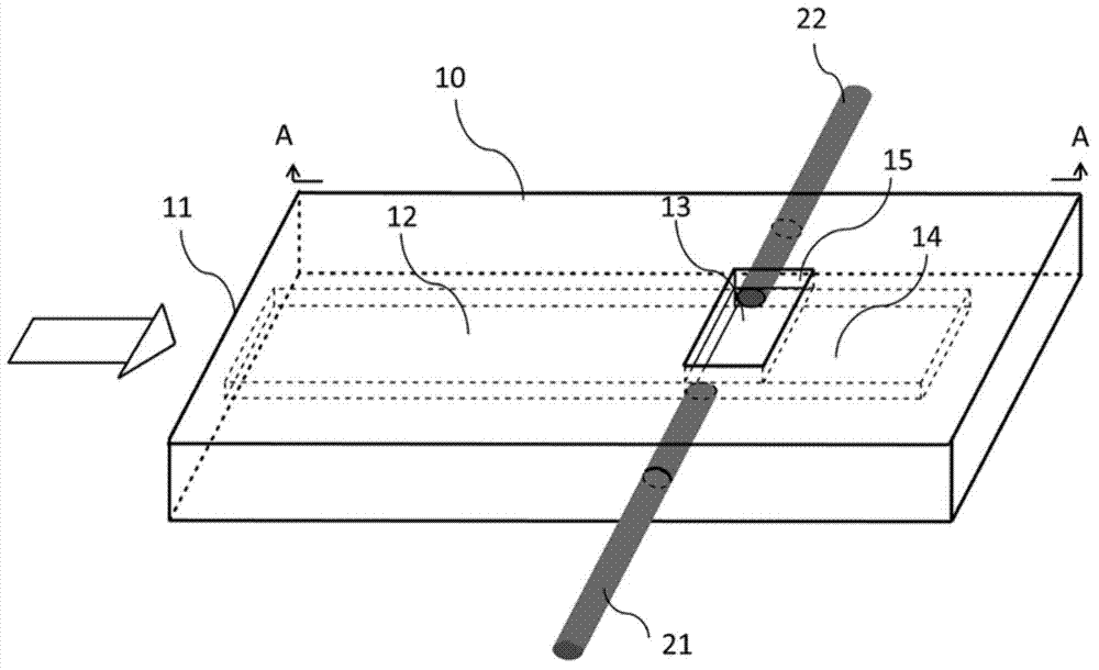
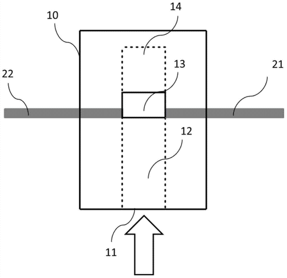
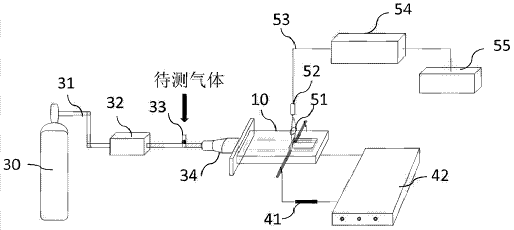
[0036] The structure of the detection system based on glow discharge plasma excitation spectrum in this embodiment is as follows: figure 1 , figure 2 , image 3 shown. The spectrum detection system consists of a sampling system; a power supply 41, a plasma generator 10 that generates glow discharge under atmospheric pressure; a detection system that collects, transmits, splits, and detects the detection light excited by the plasma generator; and The signal detected by the detection system is composed of a data processing system for analysis and processing. Among them, the sampling system includes: plasma maintenance gas source (gas supply cylinder or air pump) 30 , plasma maintenance gas delivery pipeline 31 , gas flow meter 32 , sampling nozzle 33 ; working gas inlet port 34 . The plasma generating device based on glow discharge includes: an air inlet cavity 12 , a discharge cavity 13 , a gas buffer cavity 14 , and two discharge ele...

Embodiment 2

[0039] Embodiment 2-principle and operation of detection

[0040] In this example, the detection system based on glow discharge plasma excitation spectrum described in Example 1 is used for the determination of organic matter. Under the condition of feeding a small amount of plasma maintaining gas or directly in the air, a DC power supply is used to apply a voltage on the two discharge electrodes, so that the working gas forms a stable plasma between the two electrodes. The breakdown voltage of the plasma is 550V when a small amount of argon plasma maintenance gas is fed in, and the breakdown voltage is 830V when it is directly ignited in air. During detection, the plasma maintenance gas argon continuously enters the gas inlet chamber inlet 11 through the gas flow meter 32 at a flow rate of 130mL / min, and flows into the discharge chamber 13 through the gas inlet chamber 12 to maintain the continuous discharge of the plasma and ensure the baseline stability. Take a certain am...

Embodiment 3

[0044] Embodiment 3-comparative test

[0045] The experiment below proves that the plasma generator based on glow discharge of the present invention can significantly improve the plasma stability and detection sensitivity compared with the existing plasma torch. Under normal temperature and pressure, using the detection operation described in Example 2, a comparative experiment was carried out with the plasma generating device described in Example 1 and the existing plasma torch.

[0046] Compared with the original plasma torch, the difference of the plasma generating device described in Embodiment 1 is that the exit direction of the plasma discharge chamber is changed, and a gas buffer chamber is added.

[0047] The plasma torch has the same discharge distance and breakdown voltage as the glow discharge-based plasma generator in Example 1, and the plasma sustaining gas is argon. The same acetone saturated vapor was detected with the plasma torch and the plasma generating dev...


PUM

PropertyMeasurementUnit
diameteraaaaaaaaaa

Abstract

The invention discloses a glow discharge-based plasma generator and a spectrum detection system formed by the glow discharge-based plasma generator; the spectrum detection system mainly comprises a sampling system, a power supply, the plasma generator, an optical detection system and a data processing system, wherein the plasma generator mainly comprises two discharge electrodes, and a working gas inlet cavity, a discharge cavity and a cushion chamber which are arranged in an insulation material generation device body and are sequentially communicated; the working gas inlet cavity has a pipe cavity structure; the side of the discharge cavity vertical to the working gas inlet direction has an open structure; the two discharge electrodes are oppositely arranged at the two sides along the other direction of the discharge cavity; the side of the cushion chamber facing the working gas inlet direction is a closed surface; the working gas enters through the gas inlet cavity, is ionized by the discharge cavity arranged between the two discharge electrodes and then is discharged outside from an opening of the discharge cavity; the glow discharge-based plasma generator is simple in structure, small in volume, low in power and low in gas consumption, and has the tendency of being developed into portable equipment.

Description

Technical field [0001] The invention belongs to the field of analytical chemical spectrum analysis, and in particular relates to a glow discharge-based plasma generator and a plasma excitation spectrum detection system composed of it, which can be applied to the analysis and detection of organic and inorganic substances. Background technique [0002] The emission spectroscopic detection method is to use the characteristic spectral lines and their intensities generated during the excitation and transition of the substance to realize the detection of the composition and content of the substance. At present, the excitation light sources commonly used in the emission spectroscopy detection method mainly include DC arc, low-voltage AC arc, high-voltage capacitor spark and inductively coupled high-frequency plasma source. However, these excitation light sources are bulky, high in power, and high in detection cost, making it difficult to realize miniaturization and portability, and...

Claims


Application Information

Patent Timeline
Patent Type & Authority Applications(China)
IPC IPC(8): G01N21/73
Inventor 段忆翔李雪梅孟凡英
Owner SICHUAN UNIV
Why Eureka
Try Eureka