Method for extracting shale oil gas by oil shale in-situ topochemical method

A technology for shale oil and gas and oil shale, which is applied in the field of oil shale in-situ local chemical extraction of shale oil and gas, can solve the problems of difficult control of the reaction process, large excavation workload, large heat loss, etc., so as to reduce the production cost. and commercial risks, reducing construction difficulty and cost, and improving operability

Active Publication Date: 2014-05-14
JILIN UNIV +1
View PDF16 Cites 32 Cited by
  • Summary
  • Abstract
  • Description
  • Claims
  • Application Information

AI Technical Summary

Problems solved by technology

However, there are many disadvantages in the production of shale oil by surface dry distillation: heavy excavation workload and high cost; easy to form gobs, leading to land subsidence; difficult to deal with a large amount of residue, large accumulation, easy to cause secondary pollution; discharge a large amount of waste gas and Sewage pollutes the environment heavily; water consumption is large, etc.
Although this kind of complete underground combustion can provide a large amount of heat for the cracking of kerog

Method used


Image

  • Method for extracting shale oil gas by oil shale in-situ topochemical method
  • Method for extracting shale oil gas by oil shale in-situ topochemical method
  • Method for extracting shale oil gas by oil shale in-situ topochemical method

Examples


example 1

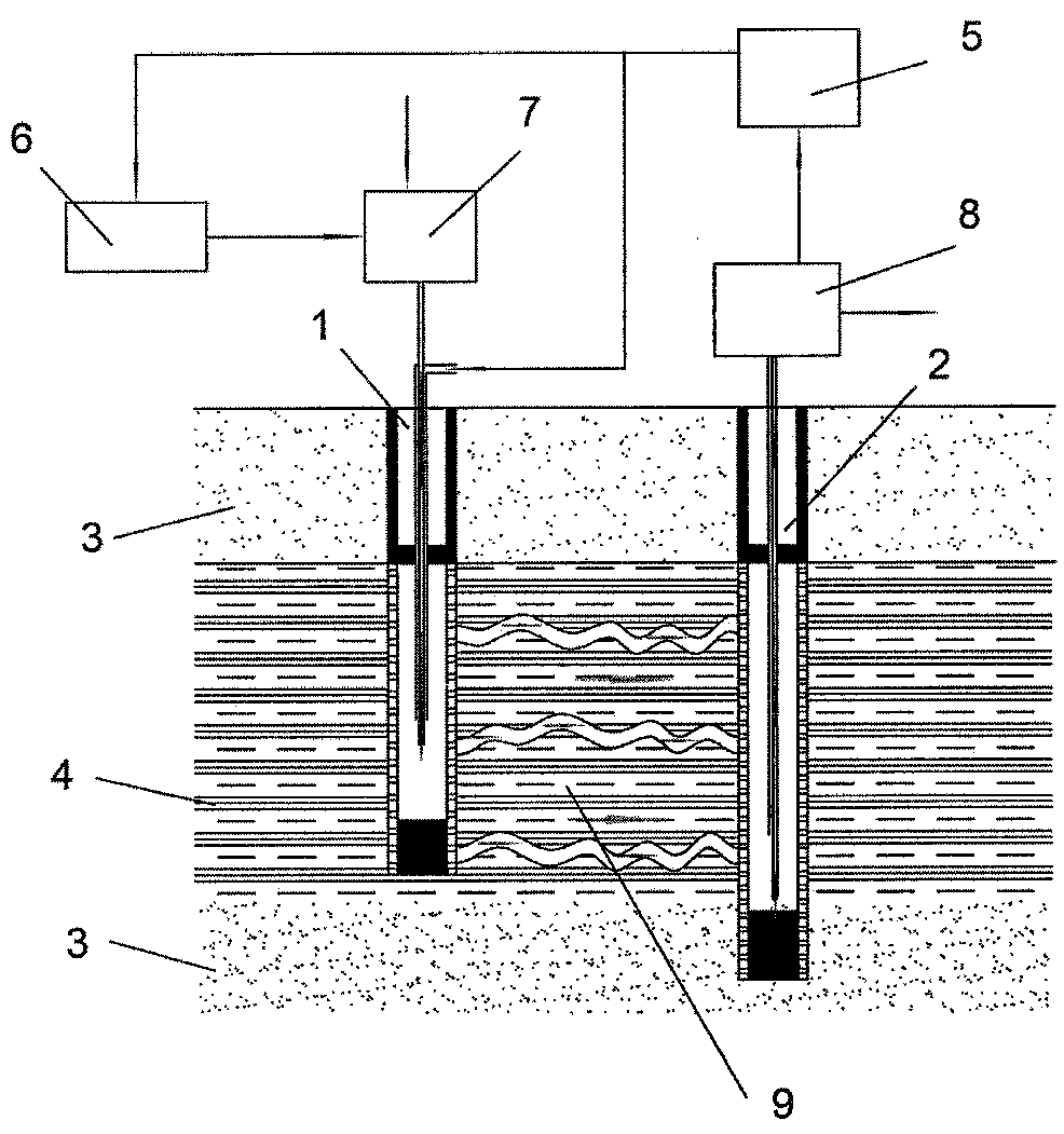
[0029] Example 1: if figure 1 Shown, be double well form, the specific steps of the present embodiment are as follows:

[0030] (1) Drilling and Completion:

[0031] a. Drill two wells, one well is the heat injection well 1, and the other well is the production well 2, and the distance between the boreholes of the two wells is 25m;

[0032] b. Drill two wells with the same technology, the hole diameter is 150mm, the hole diameter is 150mm from 0 to 65m, and a 146mm casing is installed; The direction points to another well, the well is cemented between the casing and the well wall, and the cement base is poured at the bottom of the well;

[0033] c. The two wells are connected through hydraulic fracturing fractures, and the production well and the heat injection well can be interchanged during the implementation process;

[0034] d. An injection channel should be formed in the heat injection well 1, and a gas outflow channel and an oil pumping channel should be formed in the...

example 2

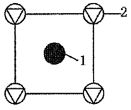
[0055] Example 2: if Figure 4 As shown, the group well mode, the specific steps of the present embodiment are as follows:

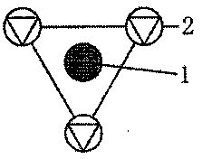
[0056] a. According to the distribution and trend of the oil shale layer, select the specific locations of the heat injection wells and production wells, arrange 24 production wells 2 and 7 heat injection wells 1 in the delineated working area, and the plane distribution of the production wells 2 is 7 six 7 heat injection wells 1 are located in the middle of 7 hexagonally distributed production wells 2, the distance between adjacent production wells 2 and production wells 2 is 25m, and the distance between adjacent heat injection wells 1 and production wells 2 The distance is 25m;

[0057] b. The production wells 2 are distributed in a hexagon with the heat injection well 1 as the center;

[0058] c. Each heat injection well 1 and production well 2 are connected through hydraulic fracturing fractures;

[0059] d. A gas injection channel should be form...


PUM


Abstract

The invention discloses a method for extracting shale oil gas by an oil shale in-situ topochemical method. The method includes: a partial chemical reaction area is formed in an underground oil shale stratum via hot mixed gas; in the whole process, a series of 'chain reactions' are induced by means of controlling concentrations of injected hot mixed gas and recovered hot mixed gas, and along with gradual temperature rising and range widening of the reaction area, porosity and permeability of the oil shale stratum increase continuously, heat strengthening reaction processing is realized finally, and self catalytic cracking of the oil shale stratum from inner to outer is achieved to generate shale oil and fuel gas. After the chain reactions are over, fixed carbon in the oil shale stratum is continuously enabled to react to generate low-heating-value gas via the hot mixed gas, high-temperature waste heat in the area finished in cracking reaction is recycled, and self-supporting and maximal utilization of energy for the oil shale stratum cracking are realized. By the aid of the method, exploring method, environmental harms and commercial risks can be reduced.

Description

technical field [0001] The invention relates to an oil shale mining technology, in particular to a method for extracting shale oil and gas by in-situ local chemical reaction of oil shale. Chemical reaction is used to crack the organic matter in oil shale to extract shale oil and fuel gas, and high waste heat is recycled to the area where the cracking reaction is completed. It is a method that can realize energy self-sufficiency and heat utilization rate maximization of in-situ cracking of oil shale. This technical method can be widely used in in-situ mining of solid or condensed mineral fuels (oil shale, coal, heavy oil). Background technique [0002] Over the past two decades, the global demand for energy has grown rapidly, and oil prices have repeatedly hit new highs. In 2012, the global consumption of crude oil reached 89.05 million barrels per day. The U.S. Energy Administration predicts that by 2030, the world’s crude oil production will reach its peak and then declin...

Claims


Application Information

Patent Timeline
IPC IPC(8): E21B43/241
Inventor 孙友宏白奉田阿龙.巴尔李强刘宝昌郭威郭明义侯传彬王秋雯高科
Owner JILIN UNIV
Why Eureka
Try Eureka