

Integrated micro-fluidic chip used for fluorescence detection of enzyme catalysis product and application thereof
A microfluidic chip and fluorescence detection technology, applied in the direction of fluorescence/phosphorescence, laboratory containers, chemical instruments and methods, etc., can solve the problems of affecting enzyme-catalyzed reactions, changing reactions, and difficulty in obtaining fluorescent substrates, etc., to achieve Improve sensitivity, reduce analysis errors, and avoid mutual interference effects
- Summary
- Abstract
- Description
- Claims
- Application Information
AI Technical Summary
Problems solved by technology
Method used
Image

Examples
Embodiment 1
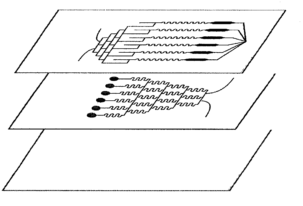
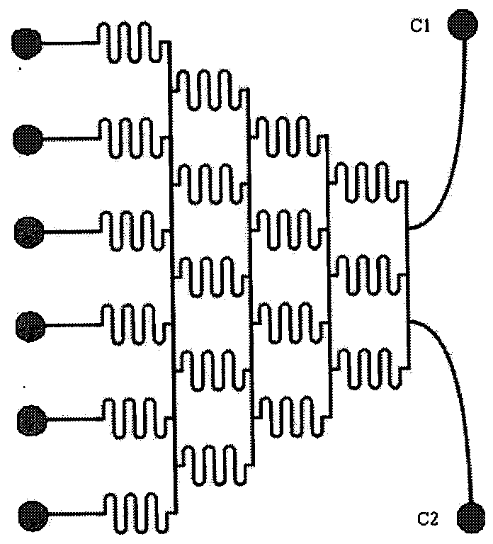
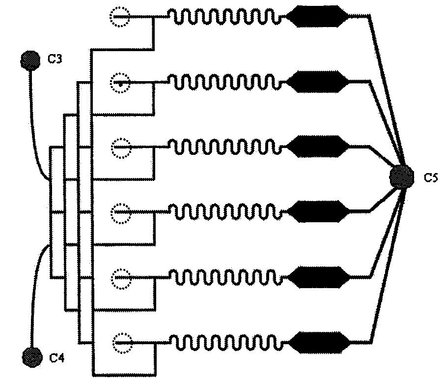
[0032]Connect the needles of the dual-channel micro-injection pump to the chip input ports C1 and C2 respectively, the input ports C3 and C4 are opened, and the liquid flows out of the chip through the input ports C3 and C4 and the waste liquid port C5. Rinse the channel with 0.1M NaOH for 30min, wash with distilled water and then rinse with 0.1M HCl for 30min, and finally rinse the chip channel with 0.01PBS buffer solution.
[0033] After the flushing of the above-mentioned channels is completed, the input ports C3 and C4 are closed, and the liquid flows out of the chip through the waste liquid port C5. Through input ports C1 and C2, BSA (1 mg / mL) was input into the microchannel network on the lower layer of the chip at a constant flow rate of 10 μL / min, and left to stand for 3.5 hours. Then, a mixed solution of protein A (20 μg / mL) and 1% glutaraldehyde, and a solution of rabbit immunoglobulin IgG (5 μg / mL dissolved in 0.01M PBS) were sequentially injected, and incubated for...
Embodiment 2
[0036] According to the operation steps described in Example 1, urease was fixed in the channel of the microfluidic chip, the chip was placed in a constant temperature bath at 37°C, and the needles of the two dual-channel micro-injection pumps were respectively connected to the input ports C1, C2; C3 on the chip. , C4 connection pipeline connected. Two 0.2M phosphate buffer solutions with different concentrations of urea (0mM, 0.5mM) were input into the lower microchannel network at a constant flow rate of 10 μL / min through input ports C1 and C2. Six columns of urea solutions with different concentrations are generated by the concentration gradient generation unit, and contact with the urease immobilized on the channel for enzymatic reaction. After incubation for 3 minutes, the urea is hydrolyzed by the enzyme to generate ammonia, which is brought to the upper microchannel network through 6 interconnected holes. At the same time, the OPA reagent (i.e. the fluorescent derivati...
Embodiment 3
[0038] According to the operation steps described in Example 1, urease was fixed in the channel of the microfluidic chip, the chip was placed in a constant temperature bath at 37°C, and the needles of the two dual-channel micro-injection pumps were respectively connected to the input ports C1, C2; C3 on the chip. , C4 connection pipeline connected. From the input ports C1 and C2, two different concentrations of acetylhydroxamic acid (0mM, 0.1mM) and 0.2M phosphate buffer solution of the same concentration of urea (0.1mM) were injected into the lower microchannel at a constant flow rate of 10μL / min The internet. The concentration gradient generation unit generates 6 rows of solutions of acetyl hydroxamic acid and the same concentration of urea, which contact with the urease immobilized on the channel for enzymatic reaction, and at the same time, acetyl hydroxamic acid inhibits urease. After incubation for 3 minutes, the urea is hydrolyzed by the enzyme to generate ammonia, whi...
PUM
 Abstract
Description
Claims
Application Information