
Injection moulded phenolic moulding plastic for communtator

A phenolic molding compound and injection molding technology, applied in the field of phenolic molding compound, can solve the problems of easy cracking of reaming holes, inability to produce, low compression molding efficiency, etc., and achieve easy control of process parameters, environmentally friendly production process, and good product consistency Effect

Active Publication Date: 2014-05-21
广西信和新合成材料有限公司
View PDF2 Cites 11 Cited by
  • Summary
  • Abstract
  • Description
  • Claims
  • Application Information

AI Technical Summary

Problems solved by technology

The existing domestic phenolic molding compounds for commutators are limited by their performance and are not suitable for small commutators (less than 10mm in outer diameter), and most of them can only be used for compression molding, which cannot meet the requirements of injection molding. For example, the application A high-bending-strength phenolic molding compound (CN102775723A) previously applied by the author has high bending strength and impact strength, but it also has some limitations. For example, when it is used for injection molding, it will block the push rod of the injection machine and cannot be produced, and for Guaranteed dimensional stability, it can only be used for commutators with an outer diameter greater than 10mm, if the inner hole of the commutator is small (less than 3mm), it is easy to crack when reaming or finalizing
In addition, the efficiency of compression molding is much lower than that of injection molding. For example, compression molding takes 2-3 minutes per mold (holding time 75-120 seconds), while injection molding only takes 1 minute per mold (holding time 25-35 seconds). second)

Method used


Image

  • Injection moulded phenolic moulding plastic for communtator

Examples

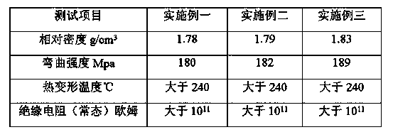

Embodiment 1

[0021] By weight, 24 parts of phenolic resin (softening point is 90-100 °C GB / T8146-2003, free phenol content is 0.5%-8% ISO8974-2002), 8 parts of hexamethylenetetramine, 2 parts of magnesium oxide , 26 parts of alkali-free glass fiber (average diameter of 8-9μm, average length of 2-6mm), 1 part of stearic acid, 36 parts of wollastonite and 3 parts of polyurethane (model MH-T80, granular, mesh number 75 -300 mesh) After the ingredients are mixed, enter the single-screw extruder (the machine model is WF100, the temperature zone is divided into three sections, the first section feeds preheating, the second section kneads and plasticizes, the third section kneads and homogenizes and discharges ) extrusion, wherein the three-stage temperature of the screw extruder is respectively set to: 45°C for the first stage, 98°C for the second stage, and 85°C for the third stage. Injection molding phenolic molding compound for commutators.

Embodiment 2

[0023] By weight, 20 parts of phenolic resin, 7 parts of hexamethylenetetramine, 1 part of magnesium oxide, 1 part of calcium oxide, 30 parts of alkali-free glass fiber, 0.5 part of stearic acid, 1 part of calcium stearate, 36.5 Part of mica powder and 3 parts of polyurethane batching mix, production process is identical with embodiment one.

Embodiment 3

[0025] By weight, 15 parts of phenolic resin, 6 parts of hexamethylenetetramine, 2 parts of magnesium oxide, 33 parts of alkali-free glass fiber, 1 part of zinc stearate, 36 parts of talcum powder, and 3 parts of polyurethane ingredients are mixed to produce The process is the same as in Embodiment 1.


PUM

PropertyMeasurementUnit
softening pointaaaaaaaaaa
diameteraaaaaaaaaa
lengthaaaaaaaaaa

Abstract

The invention discloses an injection moulded phenolic moulding plastic for a commentator. The injection moulded phenolic moulding plastic comprises the following components in parts by weight: 15-24 parts of phenolic resin, 3-8 parts of a curing agent, 1-3 parts of a curing accelerator, 25-33 parts of reinforced fibers, 0.5-2 parts of a releasing agent, 10-45 parts of inorganic filler and 1-5 parts of a flexibilizer. The phenolic moulding plastic can be used for an injection moulding machine, so that the moulding efficiency is greatly improved. The mould is not sticky, the bending strength of the moulded product reaches up to over 180Mpa, the thermal deformation temperature is greater than 240 DEG C, and the insulation resistance is greater than 1011 ohms.

Description

technical field [0001] The invention belongs to the field of phenolic molding compounds, and in particular relates to an injection molding phenolic molding compound for a commutator. Background technique [0002] The commutator is an important component of the motor, and the phenolic molding compound used for the commutator should have good electrical properties, heat resistance, mechanical strength and dimensional stability. The existing domestic phenolic molding compounds for commutators are limited by their performance and are not suitable for small commutators (less than 10mm in outer diameter), and most of them can only be used for compression molding, which cannot meet the requirements of injection molding. For example, the application A high-bending-strength phenolic molding compound (CN102775723A) previously applied by the author has high bending strength and impact strength, but it also has some limitations. For example, when it is used for injection molding, it wil...

Claims


Application Information

Patent Timeline
Patent Type & Authority Applications(China)
IPC IPC(8): C08L61/06C08L75/04C08K13/04C08K7/14B29C47/92B29C48/92
CPCB29C48/92B29C48/875B29C2948/92704B29C2948/92895
Inventor 邱维
Owner 广西信和新合成材料有限公司
Learn More