
Hydraulic control feeding system and hydraulic control feeding method

A feeding system and hydraulic technology, applied in the direction of fluid pressure actuators, mechanically driven excavators/dredgers, hoisting devices, etc., can solve the problems of increased construction costs, high cost, and large pressure loss, and achieve improved Resetting speed, improvement of construction efficiency, effect of less pressure loss

Active Publication Date: 2014-05-21
XCMG CONSTR MACHINERY
View PDF6 Cites 15 Cited by
  • Summary
  • Abstract
  • Description
  • Claims
  • Application Information

AI Technical Summary

Problems solved by technology

[0004] Using the above-mentioned oil cylinder feeding method, the oil cylinder invades the mud together with the milling device, which requires very high sealing, anti-corrosion, impact resistance and other aspects of the oil cylinder. Once the oil cylinder leaks, it will cause damage to the entire hydraulic system. Therefore, for the hydraulic system and The tightness of the oil cylinder has very high requirements; and the length of the oil supply pipe of the oil cylinder can reach tens of meters or even hundreds of meters, the pressure loss is large, the power loss is large, and the construction cost is increased.
At the same time, in the process of changing the stroke of the oil cylinder, the retraction of the oil cylinder needs to lift the milling device away from the support surface at the same time. The process of travel not only consumes a lot of power, but also takes a long time
According to the analysis, this solution has problems such as high technical difficulty, high cost and large power loss.

Method used

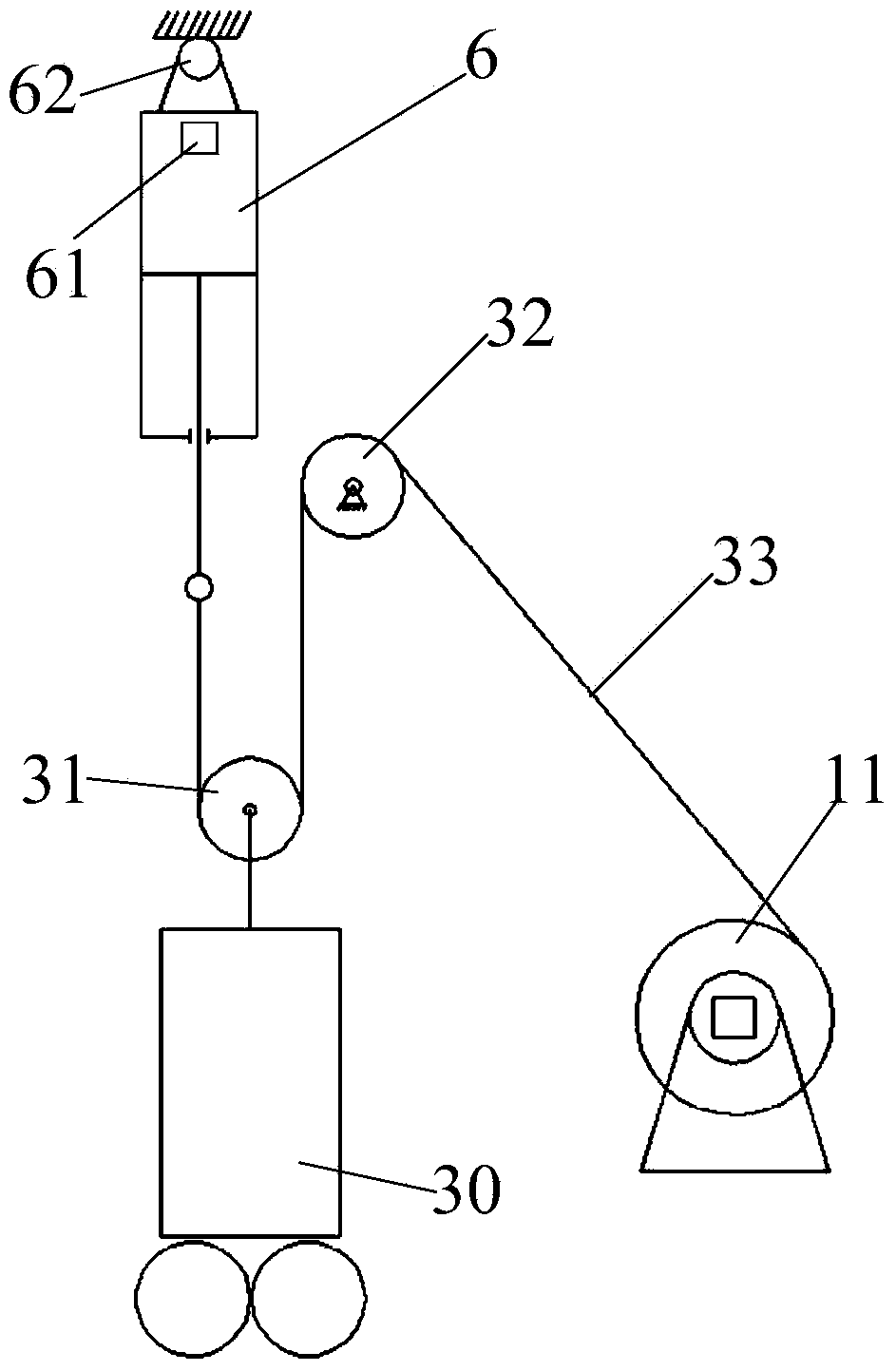
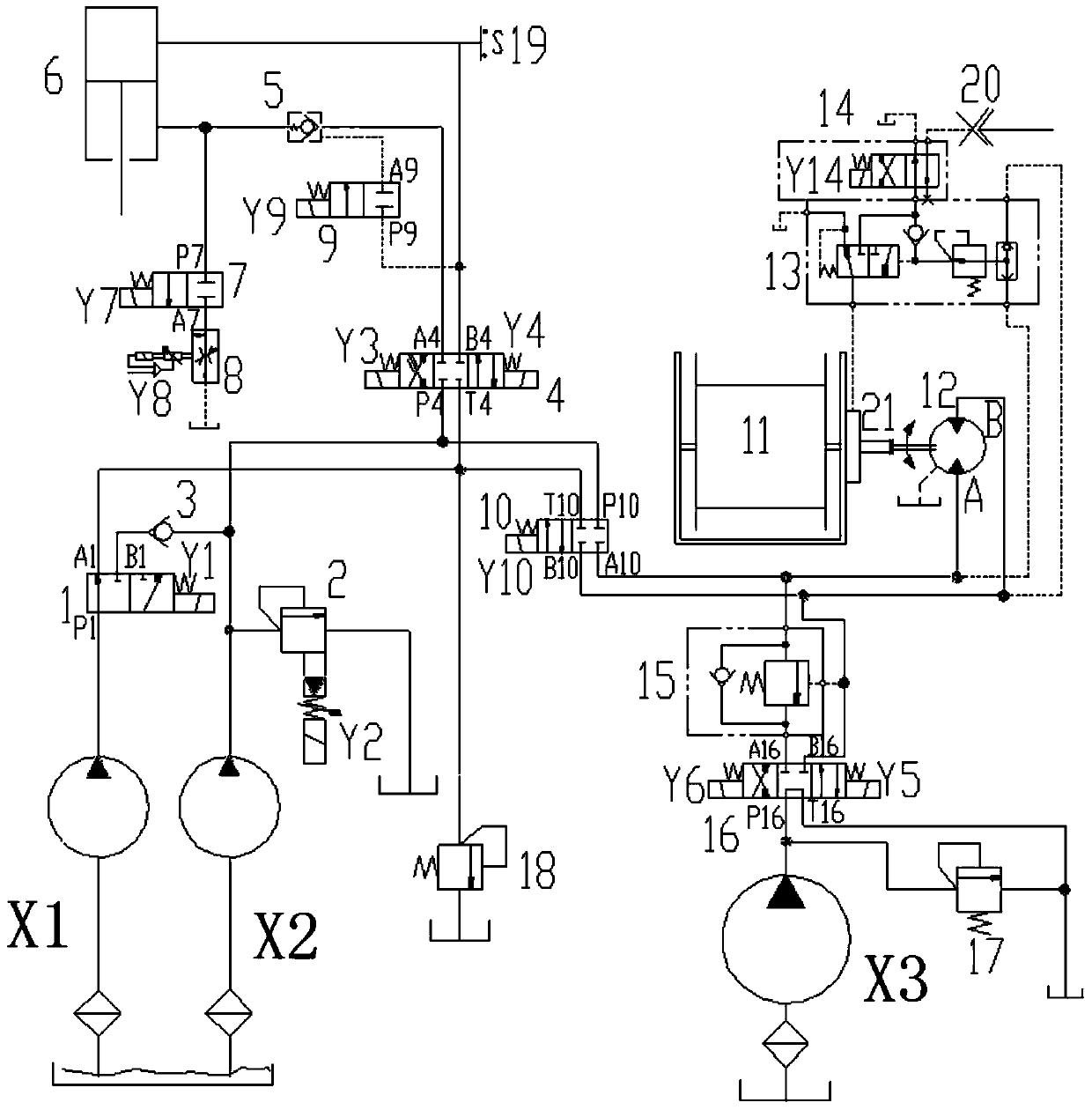
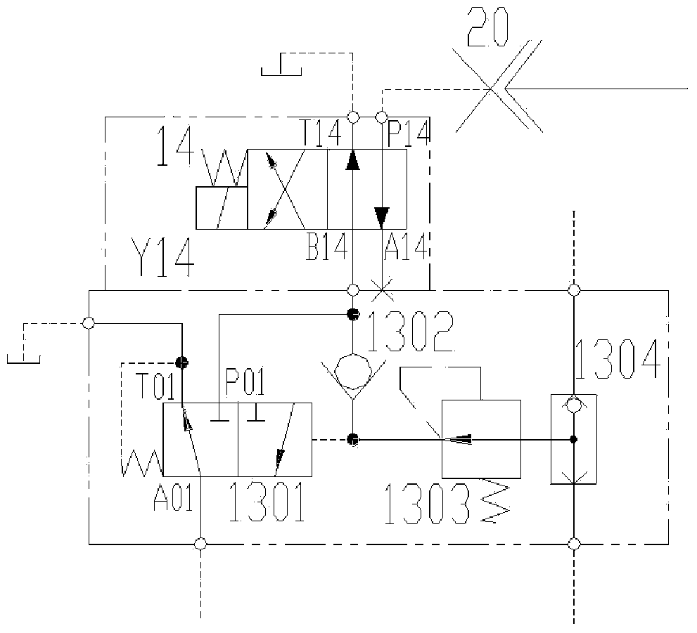

Image

  • Hydraulic control feeding system and hydraulic control feeding method
  • Hydraulic control feeding system and hydraulic control feeding method
  • Hydraulic control feeding system and hydraulic control feeding method

Examples


Embodiment Construction

[0066] The technical solutions in the embodiments of the present invention will be clearly and completely described below in conjunction with the drawings in the embodiments of the present invention. Apparently, the described embodiments are only some of the embodiments of the present invention, not all of them. Based on the embodiments of the present invention, all other embodiments obtained by persons of ordinary skill in the art without creative efforts fall within the protection scope of the present invention.

[0067] The hydraulic control feed system provided by the present invention includes a hydraulic pump assembly, a first actuator, a second actuator, a pulley assembly, and a feed device; a second reversing valve is arranged on the oil circuit where the hydraulic pump assembly is connected to the first actuator , through the second reversing valve to control the on-off and reversing of the oil circuit between the hydraulic pump assembly and the first actuator; the fi...


PUM


Abstract

The invention relates to a hydraulic control feeding system and a hydraulic control feeding method. The system comprises a hydraulic pump component, a first executing element, a second executing element, a pulley component and a feeding device, wherein a second reversing valve is arranged on an oil way for connecting the hydraulic pump component and the first executing element; the on-off state of the oil way between the hydraulic pump component and the first executing element is controlled by the second reversing valve; a fifth reversing valve is arranged on the oil way for connecting the hydraulic pump component and the second executing element; the on-off state of the oil way between the hydraulic pump component and the second executing element is controlled by the fifth reversing valve; the first executing element and the second executing element are both connected with the feeding device through the pulley component; a differential relation can be formed between the first executing element and the second executing element. The hydraulic control feeding system and the hydraulic control feeding method do not require the executing elements, and have high corrosion resistance, high sealing performance, impact resistance and the like, the pressure loss is low, the power loss is low, the construction cost is low, and the stable feeding of the feeding device can be guaranteed.

Description

technical field [0001] The invention relates to the field of hydraulic control, in particular to a hydraulic control feed system and a hydraulic control feed method. Background technique [0002] As the most advanced equipment for underground continuous construction, double-wheel slot milling machine has been used more and more in foundation construction, especially when milling hard rock, its efficiency is more than three times that of other equipment. Even so, when milling hard rock, the footage of the double-wheel milling machine is only about half a meter per hour, which requires the double-wheel milling feed mechanism to achieve a very slow speed feed, and the double-wheel milling machine is working Among them, for rock formations with different hardness, the feed mechanism should always give different pulling forces to the milling device to prevent the milling device from milling off the slot hole. Therefore, while there are special requirements for the feed mechanism...

Claims


Application Information

Patent Timeline
IPC IPC(8): F15B11/20F15B11/04F15B13/06B66D1/44E02F5/14E02F3/26
Inventor 吴兴丛张中华
Owner XCMG CONSTR MACHINERY
Learn More