Full-optical laser ultrasonic measuring method for internal defect of material

An internal defect, laser ultrasonic technology, used in the analysis of solids using sonic/ultrasonic/infrasonic waves, can solve problems such as difficulty in detecting tiny internal defects, inability to accurately locate three-dimensional positions, and great influence on surface quality, to improve excitation Efficiency, ease of operation, directional effects

Inactive Publication Date: 2014-05-21
NANJING UNIV OF SCI & TECH
View PDF8 Cites 25 Cited by
  • Summary
  • Abstract
  • Description
  • Claims
  • Application Information

AI Technical Summary

Problems solved by technology

The electromagnetic ultrasonic testing method can only detect large conductive materials and is greatly affected by the surface quality, such as document 2 (patent application number: 201210290309.X, "Metal defect detection method for laser-electromagnetic ultrasonic nondestructive testing system") and document 3 (Optics&Laser Technology, Vol.44, 860-865 (2012), "Inspection of cracks using laser-induced ultrasound with shadow method: Modeling and validation"); Air-coupled ultrasonic testing method is limited by its principle, the probe and the detection object should keep a proper distance, ultrasonic waves will undergo two serious attenuations in the air, and the detection accuracy is poor, and it is even more difficult to detect tiny internal defects, such as literature 4 (Chinese Journal of Mechanical Engineering, Vol.44, 10-14 (2008) "Air The Development of Coupled Ultrasonic Non-destructive Testing Technology "); Laser ultrasonic testing has the advantages of non-contact, broadband, remote control, high penetration, and can simultaneously stimulate multiple modes of ultrasonic waves. It is a potential non-destructive testing technology. However, problems such as adjustment difficulties, ultrasonic directionality control and reception need to be overcome, such as document 5 (Japanese Journal of Applied Physics, Vol.40, 1477-1481 (2001), "Nondestructive detection of small internal defects in carbon steel by laser ultrasonics" ) in order to change the directionality and excitation efficiency of the ultrasonic bulk wave, the laser energy is increased to cause damage to the material surface
[0004] The above method also has a major disadvantage for detecting internal defects of materials, that is, it can only detect the existence and size of defects, and cannot accurately locate the three-dimensional position of internal defects.

Method used


Image

  • Full-optical laser ultrasonic measuring method for internal defect of material
  • Full-optical laser ultrasonic measuring method for internal defect of material
  • Full-optical laser ultrasonic measuring method for internal defect of material

Examples


Embodiment Construction

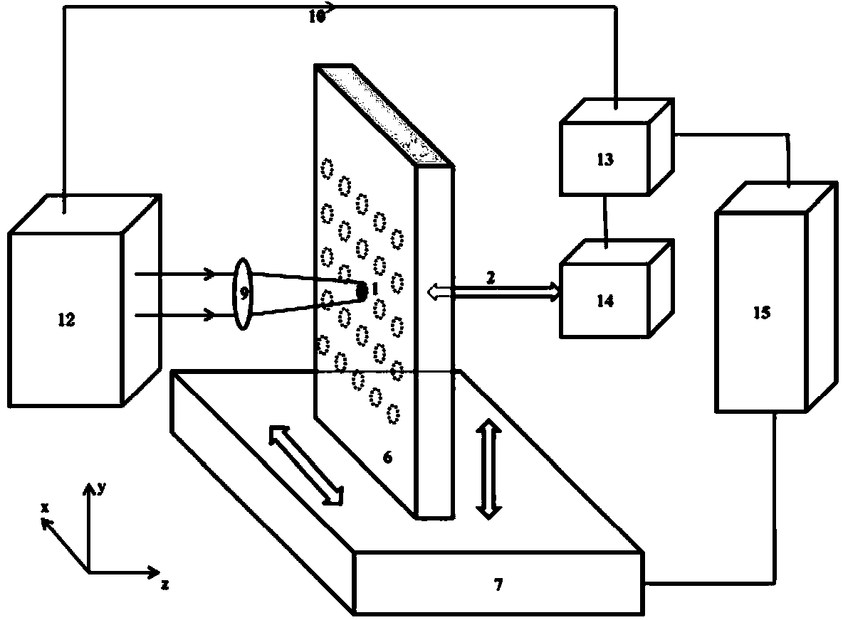
[0029] The invention is an all-optical laser ultrasonic measurement method for internal defects of materials, which comprises two steps,

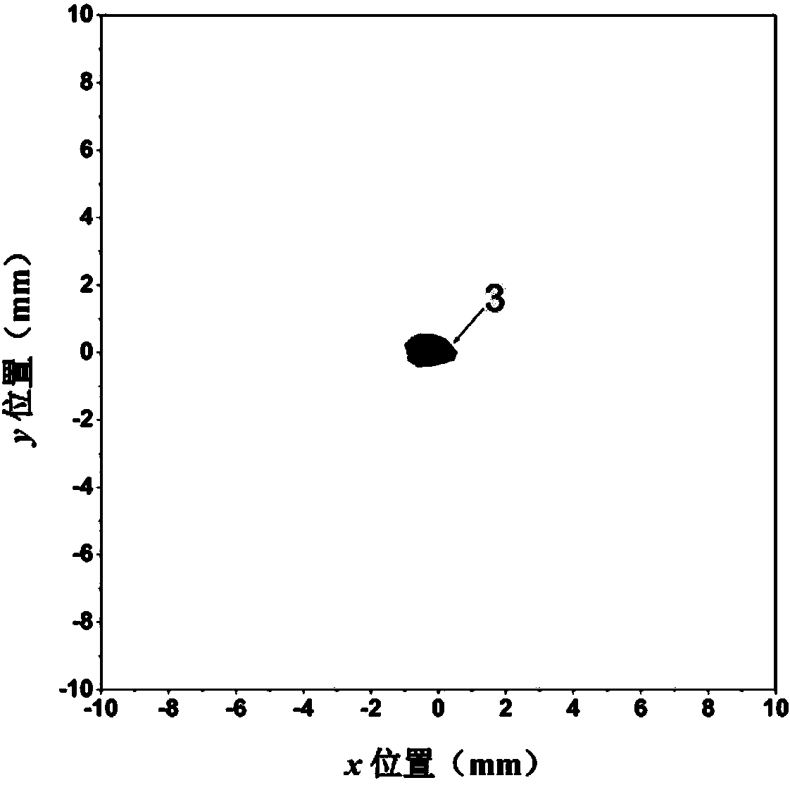
[0030] Step 1: Measure the two-dimensional position and size of the internal defect of the tested object 6 on the x-y plane;

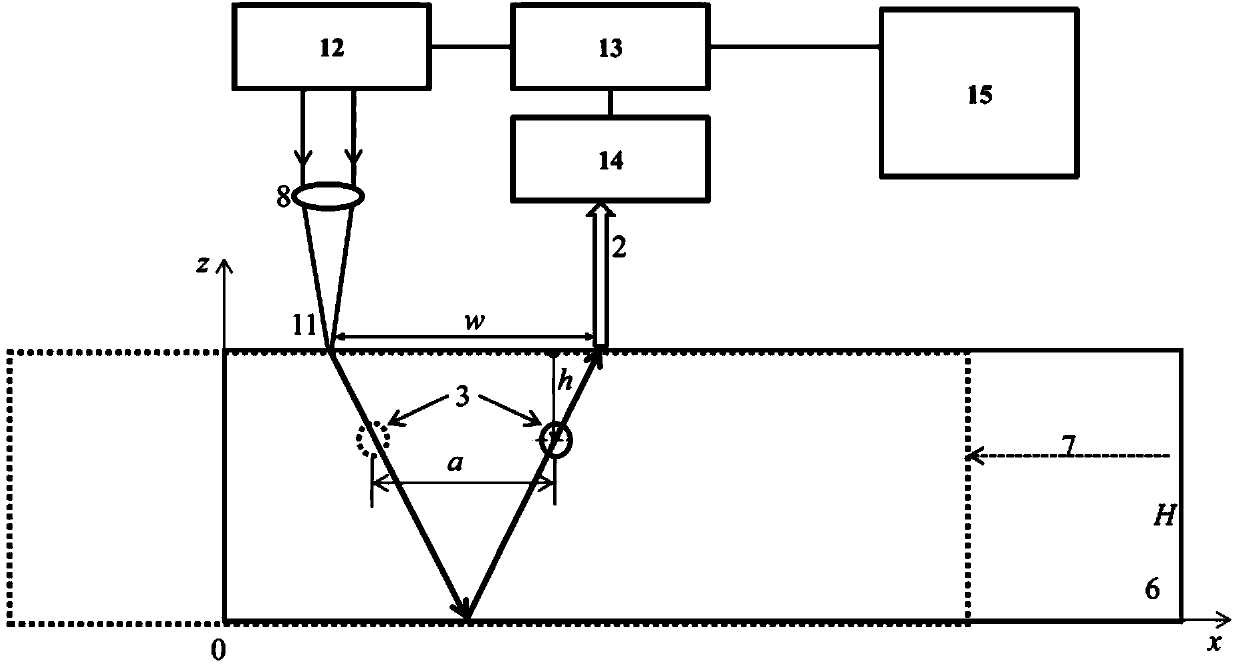
[0031] Step 2: Determining the depth of the internal defect of the tested object 6 in the z direction.

[0032] Step 1 is as specific as figure 1 As shown, the pulsed laser circular light source 1 is used to irradiate the surface of the measured object 6 to excite the ultrasonic bulk wave, and the ultrasonic bulk wave propagates to the inside of the measured object 6, and the laser vibrometer 14 is used to excite the probe light 2 on the measured object 6. The ultrasonic body wave is detected at the center of the other side, and the detection waveform of the ultrasonic body wave detected by the laser vibrometer 14 is recorded by the oscilloscope 13 connected to the laser vibrometer 14, and the measured object 6 is ...


PUM


Abstract

The invention discloses a full-optical laser ultrasonic measuring method for internal defects of a material. The method comprises the following steps: firstly, measuring the two-dimensional position and the size of the internal defect of a measured object on an x-y plane, and subsequently measuring the depth of the internal defect of the measured object in the z direction. By adopting the method, the three-dimensional position and the size information of the internal defect can be obtained by scanning, and the method is high in precision and efficiency, and is applicable to non-destructive detection on various materials.

Description

technical field [0001] The invention belongs to the technical field of laser ultrasonic non-destructive testing, in particular to an all-optical laser ultrasonic measurement method for internal defects of materials. Background technique [0002] Internal defect is a kind of defect that exists widely in various workpiece materials. If it is not detected and confirmed in time, it may lead to the fracture and damage of the workpiece, which will seriously affect the production safety. However, due to the concealment of internal defects and their extensive existence in various materials, as well as the requirements of high-precision, high-speed online inspection, harsh environment and safety inspection, it is still very difficult to carry out non-destructive inspection of internal defects. The existing conventional non-destructive testing methods mainly fall into four categories: eddy current testing, magnetic particle testing, radiographic testing and ultrasonic testing. The us...

Claims


Application Information

Patent Timeline
Patent Type & Authority Applications(China)
IPC IPC(8): G01N29/06
Inventor 沈中华孙凯华倪辰荫倪晓武徐志洪
Owner NANJING UNIV OF SCI & TECH
Why Eureka
Try Eureka