System for processing optical fiber end faces and method for processing optical fiber end faces

An optical fiber end face and optical fiber technology, applied in the coupling of optical waveguide, optics, light guide, etc., can solve the problems of unsuitable installation by users and large size of the grinding machine, so as to eliminate micro cracks, reduce surface roughness, and achieve uniformity Effect

Inactive Publication Date: 2017-02-08
TYCO ELECTRONICS (SHANGHAI) CO LTD
View PDF5 Cites 0 Cited by
  • Summary
  • Abstract
  • Description
  • Claims
  • Application Information

AI Technical Summary

Problems solved by technology

When splicing optical fibers, it is necessary to use an optical fiber grinder to process the end faces of the optical fibers to be spliced. However, due to the large size of the grinder, it is not suitable for users to install this grinder at the splicing site.

Method used


Image

  • System for processing optical fiber end faces and method for processing optical fiber end faces
  • System for processing optical fiber end faces and method for processing optical fiber end faces
  • System for processing optical fiber end faces and method for processing optical fiber end faces

Examples


Embodiment Construction

[0036] While the present invention will be fully described with reference to the accompanying drawings containing preferred embodiments of the invention, it should be understood before proceeding that those skilled in the art may modify the invention described herein while obtaining the technical effects of the present invention. Therefore, it should be understood that the above description is a broad disclosure for those skilled in the art, and its content is not intended to limit the described exemplary embodiments of the present invention. The same reference numerals in the figures denote the same components.

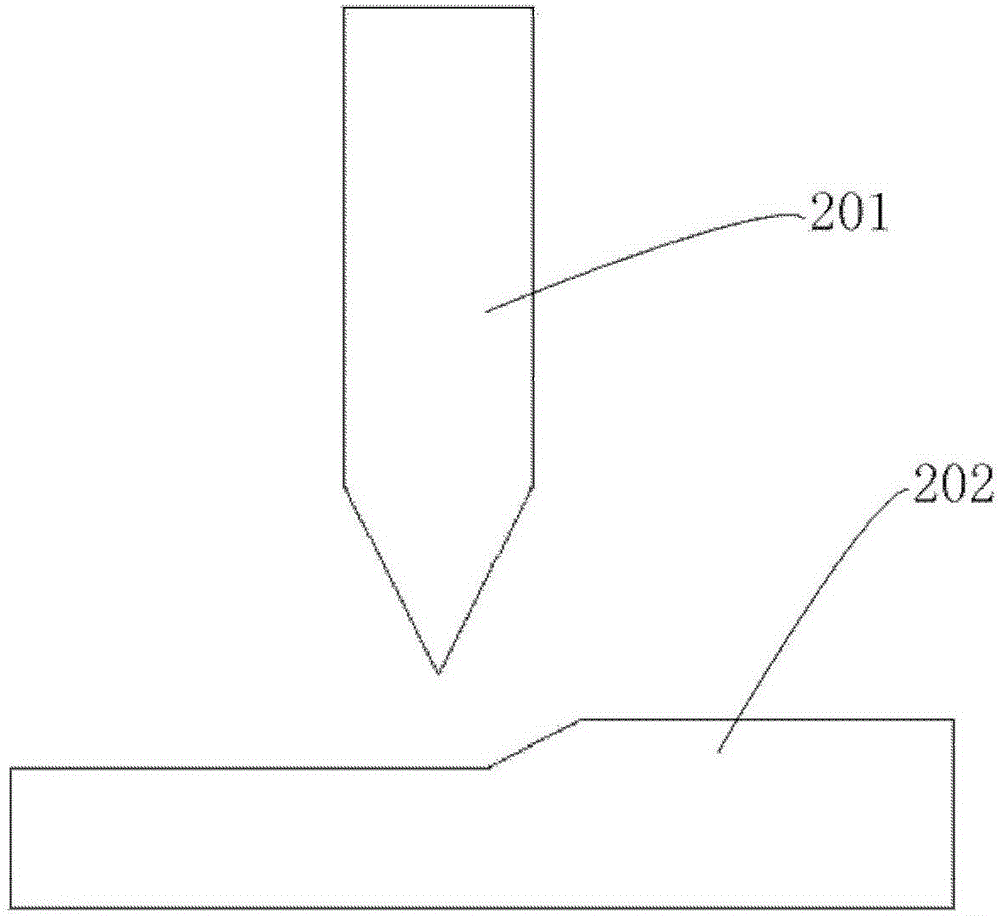
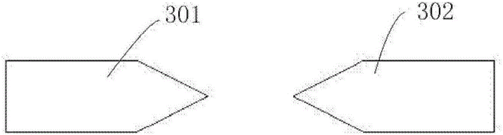
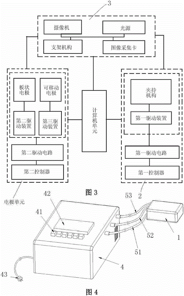
[0037] 3-7, according to a general embodiment of the present invention, a system for processing the surface of non-metallic materials such as optical fiber end faces is provided, including a plurality of electrode heads 1, each of which It includes: a plate-shaped electrode 11 with one polarity (for example, negative polarity); correspond. The tip electrode group 1...


PUM


Abstract

A system for processing an end face of an optical fiber, comprising a plurality of electrode tips, each of said electrode tips comprising: a plate electrode having one polarity; and a tip electrode set having another polarity, said The tip electrode group corresponds to the plate electrode, wherein the tip electrode group includes a plurality of tip electrodes arranged in parallel, and the plurality of tip electrodes and the plate electrode are configured to form an arc region when discharging , to process the end of the optical fiber arranged in the arc region. The present invention also provides a method for processing the end face of an optical fiber using the system for processing the end face of an optical fiber, using multi-electrodes to discharge the plate electrode to discharge the end face of the optical fiber to achieve uniformity and flexibility in processing the end face of the optical fiber.

Description

technical field [0001] The invention relates to a system for processing the end face of an optical fiber, in particular to a system for processing an end face of an optical fiber by using an electrode discharge device and a method for processing the end face of an optical fiber. Background technique [0002] In the prior art, a surface treatment technology has been proposed which uses a discharge surface treatment method to plate a corrosion-resistant and wear-resistant coating on the metal surface. E.g, figure 1 It is a schematic diagram showing the principle of a surface treatment technology based on electrode discharge in the prior art. The tip electrode 201 is opposite to the metal workpiece 202 to be processed as the ground terminal, and can realize the processing techniques such as electroplating, welding, and surface cutting on the metal workpiece 202 . [0003] For example, in the Chinese patent whose authorized publication number is CN1106902C, a kind of discharge...

Claims


Application Information

Patent Timeline
Patent Type & Authority Patents(China)
IPC IPC(8): G02B6/25H05B7/06
CPCG02B6/2551G02B6/2552C03B37/15
Inventor 蔡娅童朝阳
Owner TYCO ELECTRONICS (SHANGHAI) CO LTD
Why Eureka
Try Eureka