Eureka AIR delivers breakthrough ideas for toughest innovation challenges, trusted by R&D personnel around the world.

Method of manufacturing object with low reflection film

A technology of low-reflection film and manufacturing method, which can be applied to devices, coatings, instruments and other directions for coating liquid on the surface, which can solve the problems of difficulty in forming a low-reflection film, poor controllability of film thickness, etc., and achieve short drying or sintering time. , The effect of short coating time and excellent film thickness controllability

Inactive Publication Date: 2014-06-04
ASAHI GLASS CO LTD
View PDF4 Cites 7 Cited by
  • Summary
  • Abstract
  • Description
  • Claims
  • Application Information

AI Technical Summary

Problems solved by technology

[0020] However, if this method is used, it is difficult to form a low-reflection film with an arbitrary film thickness that can be optically designed when reducing the viscosity of the coating composition, that is, there is a problem that the film thickness controllability is poor.

Method used


Image

  • Method of manufacturing object with low reflection film
  • Method of manufacturing object with low reflection film
  • Method of manufacturing object with low reflection film

Examples


Embodiment

[0136] Hereinafter, the present invention will be further described in detail through examples.

[0137] Examples 1 to 4 are examples, and examples 5 and 6 are comparative examples.

[0138] (Average primary particle size of fine particles)

[0139] The average primary particle size of fine particles is obtained by converting the specific surface area measured by the BET method and the volume of the spherical particles assuming that the spherical particles are uniformly dispersed in the carrier.

[0140] (Average aggregation particle size of fine particles)

[0141] The average aggregated particle size of the fine particles was measured with a dynamic light scattering particle size analyzer (manufactured by Nikkiso Co., Ltd. (Nikkiso Co., Ltd., MICROTRAC UPA).

[0142] (viscosity)

[0143] The viscosity of the coating composition was measured after adjusting the liquid temperature to 25° C. with a constant temperature bath using a B-type viscometer (manufactured by Toki San...

example 1

[0175] Embossed glass (manufactured by Asahi Glass Co., Ltd., trade name: "Solite" (soda-lime glass (ultra-clear flat glass) with low iron content and high transmittance) was prepared as a base material, and embossed glass with pear skin-like patterns formed on the surface Embossed glass), size: 100mm×100mm, thickness: 3.2mm), use cerium oxide aqueous dispersion to grind and clean the pear skin pattern surface of embossed glass, wash away cerium oxide with water, rinse with ion-exchanged water, Let it dry.

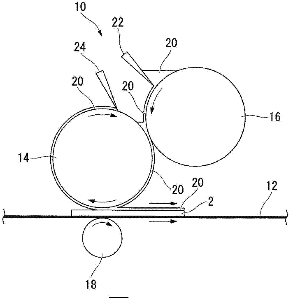
[0176]Preheat the patterned glass with a preheating furnace (manufactured by ISUZU Co., Ltd., VTR-115), and keep the glass surface temperature of the patterned glass at 30°C. On the surface, the coating composition (A) was applied by a coating roll of a reverse roll coater (manufactured by Sanwa Seiki Co., Ltd. (Sanwa Seiki Co., Ltd.). Coating conditions are as follows.

[0177] The conveying speed of the substrate: 13.8m / min,

[0178] Rotational speed of coating roller...

example 2~5

[0185] Except having changed the coating composition and coating conditions into the coating composition and coating conditions shown in Table 2, it carried out similarly to Example 1, and obtained the article which formed the low reflection film. Rate this item. The results are shown in Table 2.


PUM

PropertyMeasurementUnit
Particle sizeaaaaaaaaaa
Sizeaaaaaaaaaa
Thicknessaaaaaaaaaa

Abstract

Provided is a method of manufacturing an object with a low reflection film, with which it is possible to form a low reflection film with which it is possible to handle a wide substrate, have a comparatively rapid speed of conveyance of the substrate, a comparatively low volume of required coating compound, a comparatively short time for drying, firing, and / or application, and a uniform thickness, as well as have superior thickness controllability whereby a low reflection film having thickness which is arbitrarily optically designable is easily formed. When forming, upon a substrate (2) which is conveyed in a prescribed direction, a low reflection film by applying a coating compound (20) by a coating roll (14) of a reverse roll coater (10), the rotation speed of the coating roll (14) is made slower than the conveyance speed of the substrate (2), and the coating compound (20) includes a dispersal medium (a), fine particles (b) which are dispersed in the dispersal medium (a), and a binder (c) which is either dissolved or dispersed in the dispersal medium (a), wherein the viscosity is 1-10mPa.s.

Description

technical field [0001] The present invention relates to a method of manufacturing an article having a low reflection film on a substrate. Background technique [0002] Articles having an anti-reflection function have been put into practical use in order to reduce reflection of external light or increase light transmittance. As a method for imparting an antireflection function, there is known a method of forming a low reflection film on a base material by a wet coating method (spin coating method, spray coating method, roll coating method, etc.). [0003] The spin coating method is a method of applying the low-reflection film-forming coating composition on the base material by dropping the low-reflection film-forming coating composition on the base material, rotating the base material, and utilizing centrifugal force. [0004] The spray coating method is a method of applying the coating composition for forming a low-reflection film on a substrate by spraying the coating comp...

Claims


Application Information

Patent Timeline
IPC IPC(8): B05D5/06B05D1/28C03C17/25C09D7/12C09D201/00
CPCC03C17/007C09D7/1283B05D1/28C03C2217/42C03C2217/732G02B1/111B05D2252/00C09D7/005C09D7/42C09D7/69
Inventor 大谷义美本谷敏
Owner ASAHI GLASS CO LTD
Why Eureka
Eureka Blog
Learn More