
Read operation control signal generator and operating method thereof

A technology of control signal and read operation, which is applied in the work field of read operation control signal generator and read operation control signal generator, can solve the problems that the layout structure cannot be completely matched, the drain voltage is not completely consistent, etc., so as to reduce the layout area, The effect of reducing the number of branches and simplifying the branch

Active Publication Date: 2014-06-18
SHANGHAI HUAHONG GRACE SEMICON MFG CORP
View PDF3 Cites 4 Cited by
  • Summary
  • Abstract
  • Description
  • Claims
  • Application Information

AI Technical Summary

Problems solved by technology

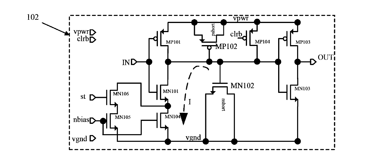
A disadvantage of the existing delay circuit 2 is that the layout structures of the NMOS transistor MN104 and the NMOS transistor MN105 cannot be completely matched (match), that is, the NMOS transistor MN105 is also connected in series with the NMOS transistor MN106, so that the drains of the NMOS transistor MN104 and the NMOS transistor MN105 Pole voltages are not exactly the same

Method used


Image

  • Read operation control signal generator and operating method thereof
  • Read operation control signal generator and operating method thereof
  • Read operation control signal generator and operating method thereof

Examples


Embodiment Construction

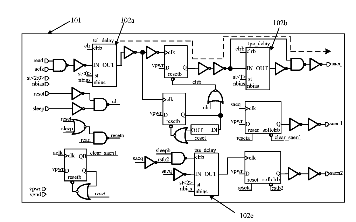
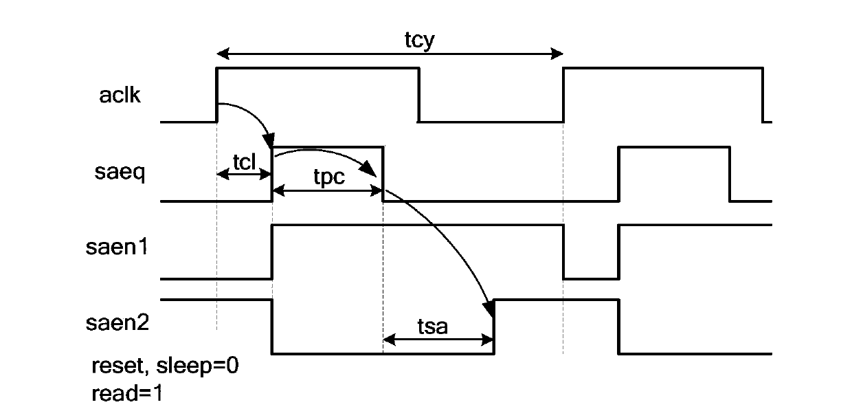
[0066] Such as Figure 4 As shown, it is a schematic diagram of a read operation control signal generator according to an embodiment of the present invention; Figure 5 Shown is the delay circuit diagram of the read operation control signal generator of the embodiment of the present invention; as Figure 6 Shown is the timing waveform when the read operation control signal generator works according to the embodiment of the present invention. The read operation control signal generator 1 of the embodiment of the present invention includes:

[0067] The first delay circuit 2a is a circuit for generating tcl_delay delay, the input end is connected to the internal clock signal aclk_in, the output end outputs the first output signal outcl, and the delay between the first output signal outcl and the internal clock signal aclk_in The time is the first delay time tcl; the internal clock signal aclk_in generates a high level when triggered by the rising edge of the external clock sig...


PUM


Abstract

The invention discloses a read-operation control signal generator. The read-operation control signal generator comprises three delay circuits with same structures and different delay time setting; the input terminal of a first delay circuit is connected with internal clock signals, three delayed output signals are generated successively by the delay circuits because of rising edge trigger of external clock signals, and signal saeq is subjected to miteinander with nonsignals of second output signals and first output signals, and then is output via a noninverting amplifier; signal saen1 is output by a noninverting amplifie via first output signals; signal saen2 is output by a noninverting amplifie via third output signals; zero clearing of the three delay circuits can be realized via rising edge trigger of external clock signals, third output signals can be delaed by a fourth delay circuit, and zero clearing signals are lower by the fourth delay circuit so as to realize zero clearing of the three delay circuits. The invention also discloses an operation method of the read-operation control signal generator. The read-operation control signal generator is simple in circuit structure, and is capable of reducing delay skew, domain area, and circuit powder consumption.

Description

technical field [0001] The invention relates to the field of semiconductor integrated circuit manufacturing, in particular to a read operation control signal generator. The invention also relates to a working method of the read operation control signal generator. Background technique [0002] The function of the read operation control signal generator in the non-volatile memory (Non-Volatile Memory, NVM) is to use the rising edge trigger of aclk to generate the three signals required for the read operation when performing the read operation (read is high level). The control signal is the signal amplification equalization signal (Sense Amplifier Equiplirium, saeq), the signal amplification enable signal (Sense Amplifier Enable, saen) one is saen1, and the signal amplification enable signal two is saen2. Such as image 3 Shown is the timing waveform diagram of the above three control signals generated by the existing read operation control signal generator. During the read op...

Claims


Application Information

Patent Timeline
Patent Type & Authority Applications(China)
IPC IPC(8): G11C16/26G11C16/06
Inventor 黄珊金建明
Owner SHANGHAI HUAHONG GRACE SEMICON MFG CORP
Learn More