Smoke waste heat exchanger and recovery device

A flue gas waste heat and heat exchanger technology, which is applied in heat exchange equipment, waste heat treatment, climate sustainability, etc. Easy installation and removal, deep utilization and long service life

Active Publication Date: 2014-06-25
北京中矿创智节能科技有限公司
View PDF9 Cites 1 Cited by
  • Summary
  • Abstract
  • Description
  • Claims
  • Application Information

AI Technical Summary

Problems solved by technology

[0003] There are the following problems in the actual application of waste heat recovery from industrial kiln exhaust: (1) It is difficult to make deep use of the waste heat of flue gas. It cannot be used in depth; some flue gas waste heat exchangers use enamel or fluoroplastic materials as heat exchanger materials in order to enhance their corrosion resistance. (2) The smoke exhaust from industrial brick kilns contains a certain amount of dust, which leads to dust accumulation or blockage of the flue gas heat exchanger

Method used


Image

  • Smoke waste heat exchanger and recovery device
  • Smoke waste heat exchanger and recovery device
  • Smoke waste heat exchanger and recovery device

Examples


Embodiment Construction

[0021] The present invention will be described in detail below in conjunction with the accompanying drawings and embodiments.

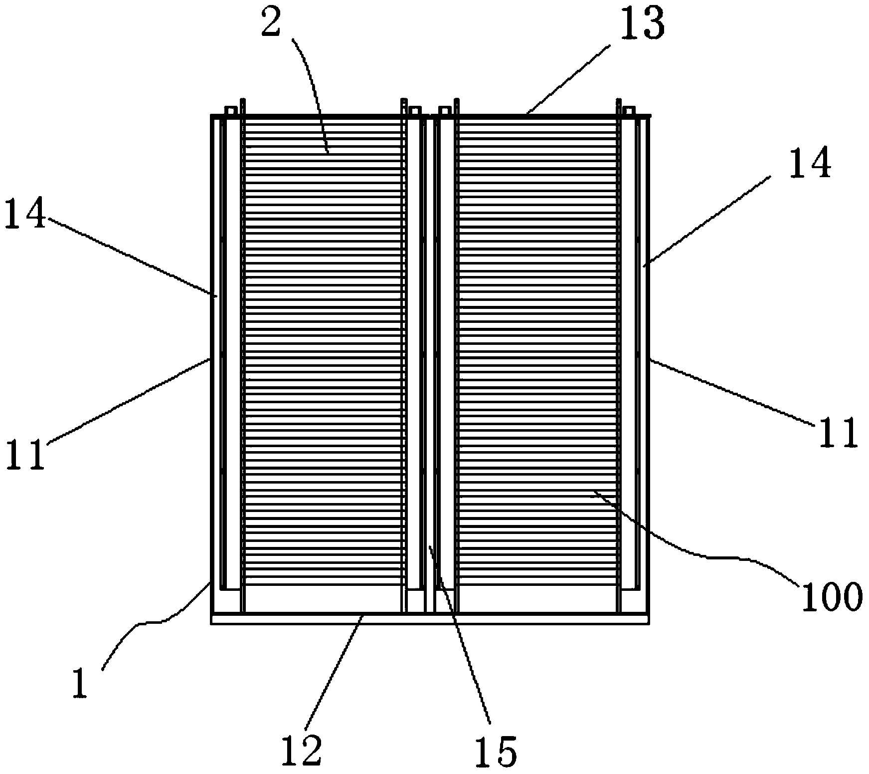
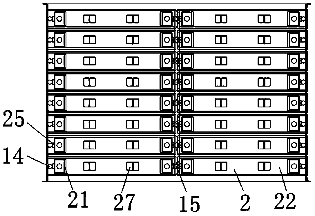
[0022] figure 1 , figure 2 The flue gas waste heat exchanger 100 provided according to the present invention is shown, the flue gas waste heat exchanger 100 includes a square cylindrical shell 1 arranged horizontally and with openings on both sides, the shell 1 is mainly composed of two side plates 11, A bottom plate 12 and a top plate 13 are formed. The inner wall of each side plate 11 is fastened to several vertically arranged slide rails 14 at equal intervals along the longitudinal direction. A plurality of vertically arranged slide rails 15 are fixedly connected between the centerlines of the bottom plate 12 and the top plate 13 at equal intervals in the longitudinal direction, and each slide rail 15 is collinear with the slide rails 14 on both sides thereof. A heat exchange module 2 is arranged between each slide rail 14 and the slide rail 15...


PUM

PropertyMeasurementUnit
Thicknessaaaaaaaaaa

Abstract

The invention relates to a smoke waste heat exchanger and recovery device for recovering kiln discharge smoke waste heat. The smoke waste heat exchanger comprises a shell body, a plurality of heat exchanging modules and a water supply-returning system. The shell body is arranged horizontally, openings in the two sides of the shell body are in a square cylinder shape, a plurality of vertically-arranged first sliding tracks are arranged at equal distance in the longitudinal direction on the inner wall of a side plate, and a plurality of vertically-arranged second sliding tracks are arranged at equal distance in the longitudinal direction between the middle line of the bottom plate and the middle line of the top plate. Each heat exchanging module comprises two pipe plates which are arranged vertically arranged at intervals and a module cover plate, the outer sides of the two pipe plates and groove type carbon steel are installed and welded to form water sleeves, the lower ends of the two water sleeves are sealed, the upper ends of the two water sleeves are openings, an opening of one water sleeve is a water inlet, an opening of the other water sleeve is a water outlet, a plurality of polished pipes which are arranged in parallel and are communicated with the water sleeves are connected between the two water sleeves, a plurality of sliding blocks are arranged on the outer sides of the two water sleeves at equal distance respectively, the heat exchanging modules are connected between the first sliding track and the second siding track collinear with the first sliding track through the sliding blocks on the two sides of the heat exchanging modules, water inlets of the heat exchanging modules are close to one side of the first sliding track, and water outlets of the heat exchanging modules are close to one side of the second sliding track.

Description

technical field [0001] The invention relates to a heat recovery device, in particular to a flue gas waste heat heat exchanger and a recovery device for recovering waste heat from exhaust gas of a kiln. Background technique [0002] Energy and environmental issues are important issues restricting social development and progress. Limited by the economic and technical level, my country's energy utilization rate is low. Coal, oil, natural gas and other energy sources are mainly consumed in the kilns of industrial enterprises. However, the exhaust gas temperature of industrial kilns is high, and a large amount of waste heat taken away by the flue gas cannot be effectively utilized. This part of waste heat is as high as 30-30% of the fuel consumption of the kiln itself. 60%, these heat energy are discharged into the atmosphere without utilization, which not only causes a great waste of heat, but also causes the temperature of the surrounding environment to become higher, forming ...

Claims


Application Information

Patent Timeline
IPC IPC(8): F27D17/00F23J15/06F28F21/08F28F19/02
CPCY02E20/30Y02P80/15
Inventor 王建学荣金利牛永胜孟杰
Owner 北京中矿创智节能科技有限公司
Why Eureka
Try Eureka