
Method for welding LED chip to ceramic body through ultrasonic waves at normal temperature
A LED chip and ultrasonic welding technology, which is applied in the manufacture of semiconductor devices, electric solid devices, semiconductor/solid devices, etc., can solve problems such as chip damage, impact on chip life, damage, etc., and achieve extended chip life, high practical value, and reduced There is the effect of lead pollution
Patent Information
- Authority / Receiving Office
- CN · China
- Current Assignee / Owner
- Publication Date
- 2014-07-02
- Estimated Expiration
- Not applicable · inactive patent
Smart Images
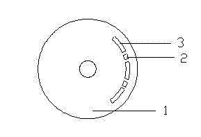
Figure 1 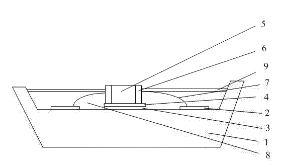
Figure 2
Abstract
Description
technical field
[0001] The invention relates to the technical field of welding processing of LED chips, in particular to a method for ultrasonically welding LED chips on a ceramic body at normal temperature. Background technique
[0002] With the country's emphasis on energy saving, especially the rapid development of the LED industry, the life expectancy of LEDs is getting higher and higher, and the welding of LED chips on ceramic materials is very important, because ceramic materials not only meet the requirements of high thermal conductivity, Corrosion resistance, high temperature resistance, wear resistance, and meet the requirements of insulation and ultra-high frequency. However, LED chips are relatively delicate, and the operating temperature of the chip is generally civilian grade: 0~+70 degrees; industrial grade: -40~+85 degrees; automotive grade: -40~+125 degrees; military grade: -55~+125 degrees . If the current commonly used reflow soldering or wave soldering i...
Examples
Embodiment Construction
[0016] The purpose and effects of the present invention will become more apparent by describing the present invention in detail below in conjunction with the accompanying drawings and embodiments.
[0017] The method for normal-temperature ultrasonic welding of LED chips on a ceramic body of the present invention comprises the following steps:
[0018] (1) Sintering palladium silver on the ceramic body 1 to form the soldering silver pad 2 and the thermally conductive silver pad 3, this step includes the following sub-steps:
[0019] (1.1) Screen printing: First, make templates for thermally conductive silver pads 2 and soldered silver pads 3, apply photosensitive glue on the screen, then put the template on the photosensitive glue, expose it through an exposure machine, and cover it with the template on the screen Exposure outside the part, the photosensitive glue is solidified, and the part covered by the template is opaque, and the photosensitive glue covered by the template...