Conventional air-conditioning operating condition distributed phase change energy storage air conditioning system

A phase-change energy storage, conventional air-conditioning technology, applied in air-conditioning systems, heating and ventilation control systems, heating and ventilation safety systems, etc. The effect of high temperature, improving efficiency and saving electricity bills

Active Publication Date: 2014-07-09
深圳乐易住智能科技股份有限公司
6 Cites 16 Cited by

AI-Extracted Technical Summary

Problems solved by technology

[0003] The most typical solution to the problems mentioned above is to carry out frequency conversion energy-saving transformation on the air conditioning system. The direct superficial beneficial effect is to reduce the power consumption of the freezing and cooling water system, but at the same time it brings a lot of negative effects to the entire air conditioning system. First, it has a certain impact on the energy efficiency ratio of the refrigeration host. Because the frequency conversion transformation redu...

Abstract

A conventional air-conditioning operating condition distributed phase change energy storage air conditioning system comprises a cooling system, an air treatment and regulation system, a distributed phase change energy storage device, an automatic control device used for controlling and coordinating the systems and pipelines connected to the automatic control device. The conventional air-conditioning operating condition distributed phase change energy storage air conditioning system is characterized in that the conventional air-conditioning operating condition distributed phase change energy storage device is arranged. Since the phase change energy storage device can be embedded seamlessly whenever and wherever, the fatal defect that a chilled water storage system is large in occupation space and cannot be popularized is overcome, the problems that an ice storage system is low in energy efficiency ratio of a main cooling unit and heat exchanging efficiency is low due to multiple heat exchanges are solved, the load of the air conditioning system can be regulated whenever and wherever, and the main cooling unit can be under an optimal operating condition constantly; if combining a peak and valley electricity price policy, the main cooling unit can be operated in the valley electricity price period annually, the power cost of the conventional air-conditioning operating condition distributed phase change energy storage air conditioning system can be comprehensively saved by 50% around as compared with that of a conventional air conditioning system.

Application Domain

Space heating and ventilation safety systemsLighting and heating apparatus +3

Technology Topic

Automatic controlAutomotive engineering +12

Image

  • Conventional air-conditioning operating condition distributed phase change energy storage air conditioning system
  • Conventional air-conditioning operating condition distributed phase change energy storage air conditioning system
  • Conventional air-conditioning operating condition distributed phase change energy storage air conditioning system

Examples

  • Experimental program(1)

Example Embodiment

[0047] 1. Phase change energy storage materials
[0048] Refrigerant hydrate
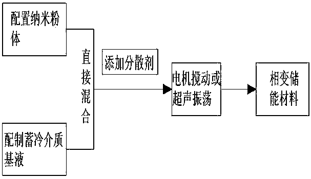
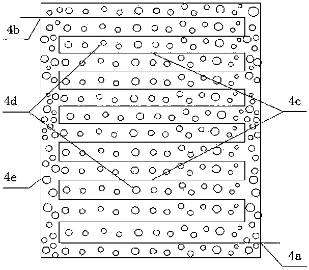
[0049] Using a three-step method, the first step will be 0.2% nano-TiO 2 , 0.3% nano Cu is mixed to make nano powder. In the second step, 23.5% HCFC-14lb, 23.5% HFC-134, 47% water is made into cold storage medium base liquid, and then the above-prepared nano powder is combined with cold storage medium base liquid. The liquid is directly mixed to make the nano-powder cold storage medium base liquid; in the third step, 3% ethylene glycol, 1% Tween-81, 1% octylphenol polyoxyethylene ether non-ionic surfactant OP- 7 Mix to make a dispersant. Finally, after mixing the nano-powder cold storage medium base liquid with the dispersing agent, it is stirred by a motor or super-vibrated to form a suspended and stable refrigerant hydrate phase change energy storage material, distributed phase change storage The energy device is filled with the phase change energy storage material (4d).
[0050] Organic phase change energy storage materials:
[0051] Using a three-step method, 0.2% nano-TiO 2 , Nano-graphite 0.3%, 0.5% Bansi 80 are mixed to make nano powder. In the second step, 59% dodecanol and 39% decanoic acid are mixed to make cold storage medium base fluid, and then the above-prepared nano powder is mixed with cold storage The medium base liquid is directly mixed to prepare the nano powder cold storage medium base liquid; the third step is to mix 0.5% Tween-81 and 0.5% octylphenol polyoxyethylene ether non-ionic surfactant OP-7. Dispersant, and finally mix the nano-powder cold storage medium base liquid with the dispersant. After the motor is stirred or super-vibrated, a suspended and stable organic phase change energy storage material is made. The distributed phase change energy storage device is filled with the Phase change energy storage materials (4d).
[0052] Inorganic phase change energy storage materials
[0053] Using a three-step method, 0.2% nano-TiO 2 , Nano-graphite 0.2%, 0.5% Bansi 80 mixed into nano powder, the second step is 20.5% calcium chloride hexahydrate, 5% glycerol, 3% silicon dioxide, 5.5% sodium hydrogen phosphate dodecahydrate , 3% acrylic acid, 1.5% sodium chloride, and 69% water are prepared into the cold storage medium base liquid, and then the above-prepared nano powder is directly mixed with the cold storage medium base liquid to make the nano powder cold storage medium base liquid; the third step , Add 0.2% nano TiO 2 , 0.2% nano-Cu composition, 0.5% Bansi 80 is mixed to make a dispersant, and finally the nano-powder cold storage medium base liquid is mixed with the dispersant, and after motor agitation or super-vibration, a suspended and stable inorganic phase change storage Energy material: The distributed phase change energy storage device is filled with the phase change energy storage material (4d).
[0054] 2. Operation mode 1 of distributed energy storage air conditioning system under conventional air conditioning conditions;
[0055] After the chilled water produced by the chiller 1 passes through the pipeline through the first water pump 1b and the second control valve 1c, it can be operated in at least three ways:
[0056] The first way is that when the cooling demand load at the end of the conventional air conditioner decreases, the water flow entering the end of the conventional air conditioner is reduced through the fifth control valve 2d, so that the relatively surplus chilled water passes through the second control valve 1c and the seventeenth in turn After the control valve 2f and the pipe connected to it enter the energy storage device 2, the relatively surplus chilled water exchanges cold and heat with the phase-change energy storage material in the energy storage device 2 for cold storage; at this time, the fourth control valve 2c and the second The water pump 2b is closed; the chilled water after the cold-heat exchange and storage is completed in turn enters the chiller 1 through the second control valve 2a, the first control valve 1a and the pipe connected to it to cool down again and restore the cooling function; the other after the water flow is reduced One way of chilled water passes through the fifth control valve 2d, the flow meter 2e, and the pipe connected to it, enters the conventional air conditioner terminal 3 through the cold water first inlet 3a, and then passes through the cold water first outlet 3b of the conventional air conditioner terminal 3 after heat exchange. , The first control valve 1a and the pipeline connected to it enter the water chiller 1 to re-cool and restore the cooling function. The feature is that the energy storage device 2 can be distributed in any position where the chilled water pipeline of the air conditioning system can be installed under normal air conditioning conditions.
[0057] The second way is, when there is no cooling load demand at any time at the end of the conventional air-conditioning part, at this time, the fifth control valve 2d is completely closed, and the chilled water flows all the way to the energy storage device 2. The running path is that the chilled water is in the first Under the power of a water pump 1b, it passes through the second control valve 1c, the seventeenth control valve 2f and the pipeline connected with it in turn, and then enters the energy storage device 2. The energy storage device 2 exchanges heat and cold with the phase change energy storage material for cold storage ; At this time, the fourth control valve 2c and the second water pump 2b are closed; after the cold storage is completed, the chilled water enters the chiller 1 through the second control valve 2a, the first control valve 1a and the pipeline connected with it in turn to cool down again, and restore the load Cooling function; It is characterized in that the energy storage device 2 can be distributed in any position where the chilled water pipeline of the air conditioning system can be installed under conventional air conditioning conditions.
[0058] The third way is that during the low peak period of power consumption at night, many areas have low peak electricity prices. If the low peak electricity price is used to store cold in the air conditioning system at night, and the cold is released during the peak electricity price period during the day, the power grid system can be shifted. Filling the valley not only ensures the safe and economical operation of the power grid, but also saves a lot of operating electricity costs for the operation of the air-conditioning system. The operation mode of this road is exactly the same as that of the second road, that is, the chilled water flows all the way to the energy storage device 2. Thermal storage is characterized in that the energy storage device 2 can be distributed in any position where the chilled water pipeline of the air-conditioning system can be installed under normal air-conditioning conditions. It is further characterized in that the operating time of the road is in the low peak power consumption period at night.
[0059] The above-mentioned three-way operation mode is the cold storage operation mode of the distributed energy storage air conditioning system under normal air conditioning conditions. After the energy storage device 2 completes the cold storage process, at this time, there are at least two cold release operation schemes.
[0060] The first solution is that when the cooling demand load at the end of the conventional air conditioner is not large, at this time, the cold storage device 2 alone provides cooling until the cooling capacity cannot meet the end load of the conventional air conditioner; the operation path is that the chilled water is in After the energy storage device 2 exchanges heat and cold with the phase-change cold storage material, it becomes a low-temperature freezing water supply under conventional air conditioning conditions. The chilled water passes through the second water pump 2b, the fourth control valve 2c, and the fifth control valve 2d in sequence. Meter 2e, the cold water first inlet 3a enters the conventional air conditioner terminal 3. At this time, the second water pump 2b runs and the second control valve 1c is closed; when the chilled water entering the conventional air conditioner terminal 3 undergoes cold and heat exchange, it becomes the conventional The relatively high-temperature frozen effluent under air-conditioning conditions enters the energy storage device 2 through the first cold water outlet 3b, the second control valve 2a, and the pipe connected to it in turn. The variable energy storage material performs cold and heat exchange to become low-temperature refrigerated water supply, and completes the cooling and cooling cycle of the chilled water until the cold storage capacity of the energy storage device 2 cannot meet the cooling capacity load of the conventional air conditioning terminal 3.
[0061] The second option is that when the cooling capacity of the conventional air conditioner terminal is extremely large, and the cold storage capacity of the energy storage device 2 cannot meet the load of the air conditioner terminal 3, it needs to be operated in conjunction with the chiller 1 for cooling and combined cooling operation The path has two chilled water cycles, that is, it is composed of the cold storage device 2 separate cooling cycle and the chiller 1 cooling cycle. The cold storage device 2 separate cooling cycle path is the same as the first solution above; the chiller 1 cooling cycle path is: When the chilled water is exchanged for cold and heat in the chiller 1, it becomes the low-temperature chilled water supply under conventional air-conditioning conditions, and the low-temperature chilled water supply sequentially passes through the first water pump 1b, the second control valve 1c, the fifth control valve 2d, the flow meter 2e, and the cold water The first inlet 3a and the pipes connected to the above-mentioned components enter the conventional air-conditioning terminal 3. When the chilled water entering the conventional air-conditioning terminal 3 undergoes cold and heat exchange, it becomes the relatively high-temperature chilled effluent under conventional air-conditioning conditions, and the chilled effluent sequentially passes through The chilled water first outlet 3b, the first control valve 1a, and the pipes connected to the above components enter the chiller 1, and the high-temperature chilled water after entering the chiller 1 exchanges cold and heat with the chiller, turning into low-temperature chilled water supply, completing chilled water The cooling-loading and cooling-supply cycle is completed until the energy storage device 2 is completely full of cooling capacity, the chiller stops operating, and the cooling release operation scheme is switched to the above-mentioned first scheme operation.
[0062] 3. Operation mode 2 of distributed energy storage air conditioning system under conventional air conditioning conditions;
[0063] The energy storage operation mode and cooling release operation scheme of the distributed energy storage air conditioning system under normal air conditioning conditions are basically the same as the operation mode 1 of the distributed energy storage air conditioning system under conventional air conditioning conditions, but the difference lies in: energy storage link Added a composite energy storage fan coil and/or composite energy storage wind cabinet and/or energy storage wall fan coil 3c in the energy storage link. While the energy storage device 2 stores cold, the composite energy storage fan Coil and/or composite energy storage wind cabinet and/or energy storage wall fan coil 3c can simultaneously participate in cold storage, which is equivalent to increasing the energy storage capacity of operation mode 1 of the distributed energy storage air conditioning system under normal air conditioning conditions In the energy release link, while the energy storage device 2 releases the cold, the composite energy storage fan coil and/or the composite energy storage wind cabinet and/or the energy storage wall fan coil 3c can simultaneously participate in the cooling; and When the chiller unit 1 provides combined cooling, the composite energy storage fan coil and/or composite energy storage wind cabinet and/or the energy storage wall fan coil 3c can simultaneously participate in the cooling, and the cooling operation plan is equivalent to Increased the cooling capacity of the distributed energy storage air conditioning system operating mode 1 under conventional air conditioning conditions.
[0064] 4. Cuboid energy storage unit
[0065] in Figure 4 In, a rectangular parallelepiped energy storage unit, characterized in that the energy storage device enclosure 4e of the cubic cold storage unit is fixed with a second cold water inlet 4a at one end, and a second cold water outlet 4b at the other end, and a second cold water outlet 4b is fixed at the other end. A cold-carrying coil 4c is connected between the inlet 4a and the second cold water outlet 4b, and the energy storage device enclosure 4e of the rectangular cold storage unit is filled with a phase-change energy storage material 4d.
[0066] 5. Tubular energy storage unit
[0067] A tubular cold storage unit. The diameter of the tube is preferably 18mm, and the length of the tube is preferably 90mm. The two ends of the tube are sealed. One end of the tube is reserved with a phase change energy storage material injection port 5a. The tube cavity is filled with phase change material 4d. The enclosure structure material of the unit can be high density polyethylene or microcapsule material.
[0068] 6. Spherical energy storage unit
[0069] A spherical cold storage unit, the diameter of the ball is preferably 90 mm, the outer surface of the ball is provided with a phase change energy storage material injection port 5a, and the material of the ball is preferably high density polyethylene or microcapsule material.
[0070] 7. Composite energy storage wind cabinet
[0071] A composite energy storage wind cabinet can be divided into three operating modes,
[0072] Operation mode 1, energy storage operation mode,
[0073] When the terminal cooling load demand of the composite energy storage wind cabinet is completely absent, the chilled water supply of the air conditioner passes through the third cold water inlet 7a, the sixth control valve 7d, the cooling coil 4c inside the energy storage device enclosure 4e, and the seventh control. The valve 7e, the third cold water outlet 7b, and the pipe connected to the above components enter the air conditioning refrigerated return water pipeline. At this time, the fifth control valve 7c, the third water pump 7g, and the eighth control valve 7f are closed; The flow in the cold-carrying coil 4c inside the device enclosure 4e exchanges cold and heat with the phase change energy storage material 4d inside the energy storage device enclosure 4e, completing the energy storage operation mode of the phase change energy storage material 4d.
[0074] Operation mode two, release cooling operation mode,
[0075] When the terminal cooling load demand of the composite energy storage wind cabinet is not large, the cold storage capacity of the phase change energy storage material 4d can fully meet the terminal cooling load demand of the composite energy storage wind cabinet, the fifth control valve 7c, the sixth control valve 7d. The seventh control valve 7e and the eighth control valve 7f are closed, and the third water pump 7g starts to run. The chilled water is carried by the cold coil 4c in the enclosing structure 4e of the energy storage device and the other part in the air-conditioning cabinet 7h. The cooling coil 4c circulates heat exchange and runs the cooling release mode until the cold storage capacity of the phase change energy storage material 4d cannot fully meet the cooling load demand at the end of the composite energy storage wind cabinet.
[0076] Operation mode three, combined cooling operation mode,
[0077] When the cold storage capacity of the phase change energy storage material 4d cannot fully meet the terminal cooling load demand of the composite energy storage wind cabinet, the fifth control valve 7c, the sixth control valve 7d, the seventh control valve 7e, and the eighth control valve 7f are opened , The third water pump 7g is turned off, and the chilled water supply runs in two ways after passing through the cold water third inlet 7a. One way is directly into the end of the air-conditioning wind cabinet 8h. The running path is: the chilled water supply passes through the cold water third inlet 7a and then passes through the fifth control. The valve 7c, the cold-carrying coil 4c in the air-conditioning wind cabinet 7h, the eighth control valve 7f, the third cold water outlet 7b and the pipes connected to the above components enter the air-conditioning chilled water return pipe network system, and complete the air-conditioning wind cabinet 7h Air conditioning process; the other way is: after the chilled water supply passes through the third cold water inlet 7a, it passes through the sixth control valve 7d, the cooling coil 4c in the energy storage device enclosure 4e, the seventh control valve 7e, and the third cold water The outlet 7b and the pipes connected with the above components enter the air conditioning chilled water return pipe network system to complete the energy storage operation mode of the phase change energy storage material 4d, until the phase change energy storage material 4d completes the energy storage, the combined cooling operation When the mode is over, when there is still cooling load demand at the end of the air-conditioning cabinet 7h, switch to operation mode 2; when there is no cooling load demand at all, and the phase change energy storage material 4d is in the energy storage state after a period of operation time, switch to Operation mode one.
[0078] 8. Composite energy storage fan coil
[0079] A composite energy storage fan coil unit can be divided into three operating modes,
[0080] Operation mode 1, energy storage operation mode,
[0081] When the cooling load demand to be borne by the composite energy storage fan coil is completely absent, the air-conditioning refrigerating water supply passes through the fourth cold water inlet 8a, the tenth control valve 8d, the cooling coil 4c inside the energy storage device enclosure 4e, The eleventh control valve 8e, the fourth cold water outlet 8b and the pipes connected to the above components enter the air conditioning refrigerated return water pipe. At this time, the ninth control valve 8c, the fourth water pump 7g, and the twelfth control valve 8f are closed; The refrigerated water supply flows in the cold coil 4c inside the energy storage device enclosure 4e for cold and heat exchange with the phase change energy storage material 4d in the energy storage device enclosure 4e to complete the energy storage of the phase change energy storage material 4d Operating mode.
[0082] Operation mode two, release cooling operation mode,
[0083] When the cooling load demand borne by the composite energy storage fan coil is not large, the cold storage capacity of the phase change energy storage material 4d can fully meet the cooling load demand borne by the composite energy storage fan coil, the ninth control valve 8c. The tenth control valve 8d, the eleventh control valve 8e, and the twelfth control valve 8f are closed, and the fourth water pump 8g starts running. The chilled water of the air conditioner is in the part of the cold coil 4c inside the energy storage device enclosure 4e. Another part of the cooling coil 4c in the fan coil 8h circulates and exchanges heat, and runs the cooling release mode until the cold storage capacity of the phase change energy storage material 4d cannot fully meet the cooling load demand of the composite energy storage fan coil End.
[0084] Operation mode three, combined cooling operation mode,
[0085] When the cold storage capacity of the phase change energy storage material 4d cannot fully meet the cooling load demand of the composite fan coil, the ninth control valve 8c, the tenth control valve 8d, the eleventh control valve 8e, and the twelfth control valve 8f is turned on, the fourth water pump 8g is turned off, the chilled water supply passes through the cold water fourth inlet 8a and then runs in two ways. One way is directly into the fan coil for 8h. The running path is: the chilled water supply passes through the cold water fourth inlet 8a and then passes through the ninth The control valve 8c, the cooling coil 4c in the fan coil 8h, the twelfth control valve 8f, the fourth cold water outlet 8b and the pipes connected to the above components enter the air conditioning chilled water return pipe network system to complete the fan coil The air conditioning process in 8h; the other way is: after the chilled water supply passes through the fourth cold water inlet 8a, it passes through the tenth control valve 8d, the cooling coil 4c in the energy storage device enclosure 4e, the eleventh control valve 8e, After the cold water fourth outlet 8b and the pipes connected with the above components enter the air conditioning chilled water return pipe network system, the energy storage operation mode of the phase change energy storage material 4d is completed, until the phase change energy storage material 4d is completely stored, the joint The cooling operation mode ends. When there is still cooling load demand at the end of the fan coil at 8h, switch to operation mode 2; when there is no cooling load demand at all, the phase change energy storage material 4d is in a state of energy storage after a period of operation time , Switch to operating mode 1.
[0086] 9. Energy storage wall fan coil
[0087] An energy storage type wall fan coil unit can be divided into three operating modes,
[0088] Operation mode 1, energy storage operation mode,
[0089] When the cooling load demand that the energy storage wall fan coil has to bear is completely absent, the air conditioning refrigerating water supply passes through the cold water fifth inlet 9a, the fourteenth control valve 9d, and the energy storage wall enclosure 9h in turn. The coil 4c, the fifteenth control valve 9e, the cold water fifth outlet 9b and the pipes connected to the above components enter the air conditioning refrigerated return pipe. At this time, the thirteenth control valve 9c, the fifth water pump 9g, and the sixteenth control Valve 9f is closed; the air-conditioning refrigerated water supply flows in the cold-carrying coil 4c inside the energy storage wall enclosure 9h to exchange cold and heat with the phase change energy storage material 4d in the energy storage wall enclosure 9h to complete Energy storage operation mode of phase change energy storage material 4d.
[0090] Operation mode two, release cooling operation mode,
[0091] When the cooling load demand borne by the energy storage wall fan coil is not large, and the cold storage capacity of the phase change energy storage material 4d can fully meet the cooling load demand borne by the energy storage wall fan coil, tenth The third control valve 9c, the fourteenth control valve 9d, the fifteenth control valve 9e, and the sixteenth control valve 9f are closed, the fifth water pump 9g starts up, and the air-conditioning chilled water is loaded inside the energy storage wall enclosure 9h The cooling coil 4a and the other part of the cooling coil 4c in the fan coil 8h circulate and exchange heat, and run the cooling release mode until the cold storage capacity of the phase change energy storage material 4d cannot be completely full of the energy storage wall fan disk When the cooling load demand of the tube ends.
[0092] Operation mode three, combined cooling operation mode,
[0093] When the cold storage capacity of the phase change energy storage material 4d cannot fully meet the cooling load demand of the energy storage wall fan coil, the thirteenth control valve 9c, the fourteenth control valve 9d, the fifteenth control valve 9e, and the The sixteen control valve 9f is opened and the fifth water pump 9g is closed. The chilled water supply runs through the fifth cold water inlet 9a and then runs in two ways. One way is directly into the fan coil for 8h. The running path is: the chilled water supply passes through the cold water fifth inlet 9a. Pass through the thirteenth control valve 9c, the cooling coil 4c in the fan coil 8h, the sixteenth control valve 9f, the fifth cold water outlet 9b and the pipes connected to the above components, and then enter the air conditioning chilled water return pipe network system , Complete the air conditioning process in the fan coil 8h; the other way is: the chilled water supply passes through the cold water fifth inlet 9a, and then passes through the fourteenth control valve 9d, and the energy storage type wall enclosure 9h in the cooling coil 4c , The fifteenth control valve 9e, the fifth cold water outlet 9b and the pipes connected to the above components enter the air conditioning chilled water return pipe network system, and complete the energy storage operation mode of the phase change energy storage material 4d until the phase change energy storage material After the 4d complete energy storage is completed, the combined cooling operation mode ends. When there is still cooling load demand at the end of the fan coil at 8h, switch to operating mode 2; when there is no cooling load demand at all, and the phase change energy storage material passes through a period of 4d After running time, it is in the state of storing energy, switch to running mode 1.
[0094] 10. Independent cold storage tank
[0095] An independent cold storage tank is characterized in that the phase change energy storage device 2 can be connected in parallel at any installable position of the chilled water supply and return pipeline to form an independent cold storage tank.

PUM

no PUM

Description & Claims & Application Information

We can also present the details of the Description, Claims and Application information to help users get a comprehensive understanding of the technical details of the patent, such as background art, summary of invention, brief description of drawings, description of embodiments, and other original content. On the other hand, users can also determine the specific scope of protection of the technology through the list of claims; as well as understand the changes in the life cycle of the technology with the presentation of the patent timeline. Login to view more.

Similar technology patents

Systems and methods for notifying multiple hosts from an industrial controller

ActiveUS8150959B1reusable block of code very difficultimprove efficiency
Owner:ROCKWELL AUTOMATION TECH

Hybrid OLED having improved efficiency

InactiveUS20080284317A1improve efficiency
Owner:GLOBAL OLED TECH

Classification and recommendation of technical efficacy words

  • save on electricity bills
  • Improve efficiency

Central management method for multi-room air-conditioner

InactiveCN1566824ASuppression of rise in peak power valuessave on electricity bills
Owner:LG ELECTRONICS (TIANJIN) APPLIANCES CO LTD

Waste gas treatment thermal cycle drying system

InactiveCN102163643Asave on electricity bills
Owner:ZHEJIANG HAFLON NEW ENERGY

Novel technique for dewatering and rinsing medical dressing by one-bath method

InactiveCN101411885Ashorten process timesave on electricity bills
Owner:宁波米杰纺织材料有限公司 +2

Solar and air source heat pump dual heat source tri-generation system

InactiveCN106016825AImprove system efficiencysave on electricity bills
Owner:山东阳光博士太阳能工程有限公司

Urban heating method in conformity with low-carbon energy policy

InactiveCN102200315Asave on electricity bills
Owner:杨铁君
Why Eureka
Try Eureka