Optical-fiber laser device

A technology of lasers and fiber gratings, applied in the field of lasers, can solve problems affecting the output effect of lasers, and achieve the effects of avoiding the reduction of laser efficiency, easy implementation, and simple structure

Inactive Publication Date: 2014-07-09
TSINGHUA UNIV
View PDF2 Cites 10 Cited by
  • Summary
  • Abstract
  • Description
  • Claims
  • Application Information

AI Technical Summary

Problems solved by technology

However, when the doping concentration of the gain fiber is low or the required laser output power is high, a longer gain fiber is required. At this time, the above-mentioned nonlinear effect and reabsorption phenomenon will also occur. Affect the output effect of the laser

Method used


Image

  • Optical-fiber laser device
  • Optical-fiber laser device

Examples


Embodiment 1

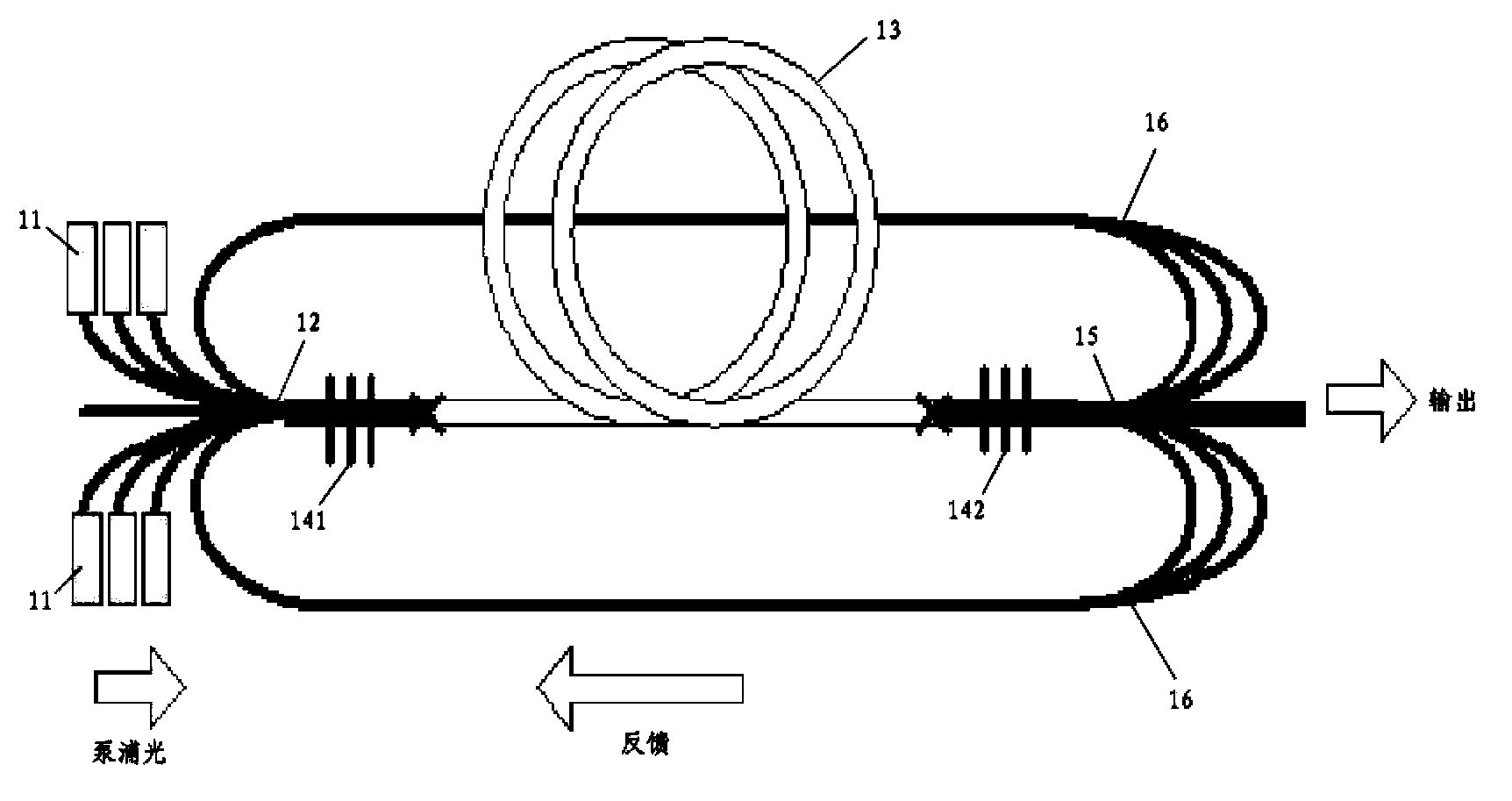
[0029] In this embodiment, the fiber laser includes: a pumping device 11, a pumping coupler, a fiber grating 14, a gain fiber 13 and a pumping feedback device, wherein:

[0030] The pump light emitted by the pump device 11 is injected into the gain fiber 13 through the pump coupler 12;

[0031] The fiber Bragg grating 14 includes a high reflection fiber Bragg grating 141 and an output fiber Bragg grating 142, and the high reflection fiber Bragg grating 141 and the output fiber Bragg grating 142 are used as cavity mirrors of the laser, and are welded to both ends of the gain fiber 13;

[0032] The length of the gain fiber 13 is shorter than the length of the fiber required to fully absorb the injected pump light, so as to ensure 10% to 50% of the residual pump light;

[0033] The pump feedback device feeds back the residual pump light at the end of the gain fiber 13 to the pump injection end, and injects it into the gain fiber 13 again.

[0034] The pump feedback device includ...

Embodiment 2

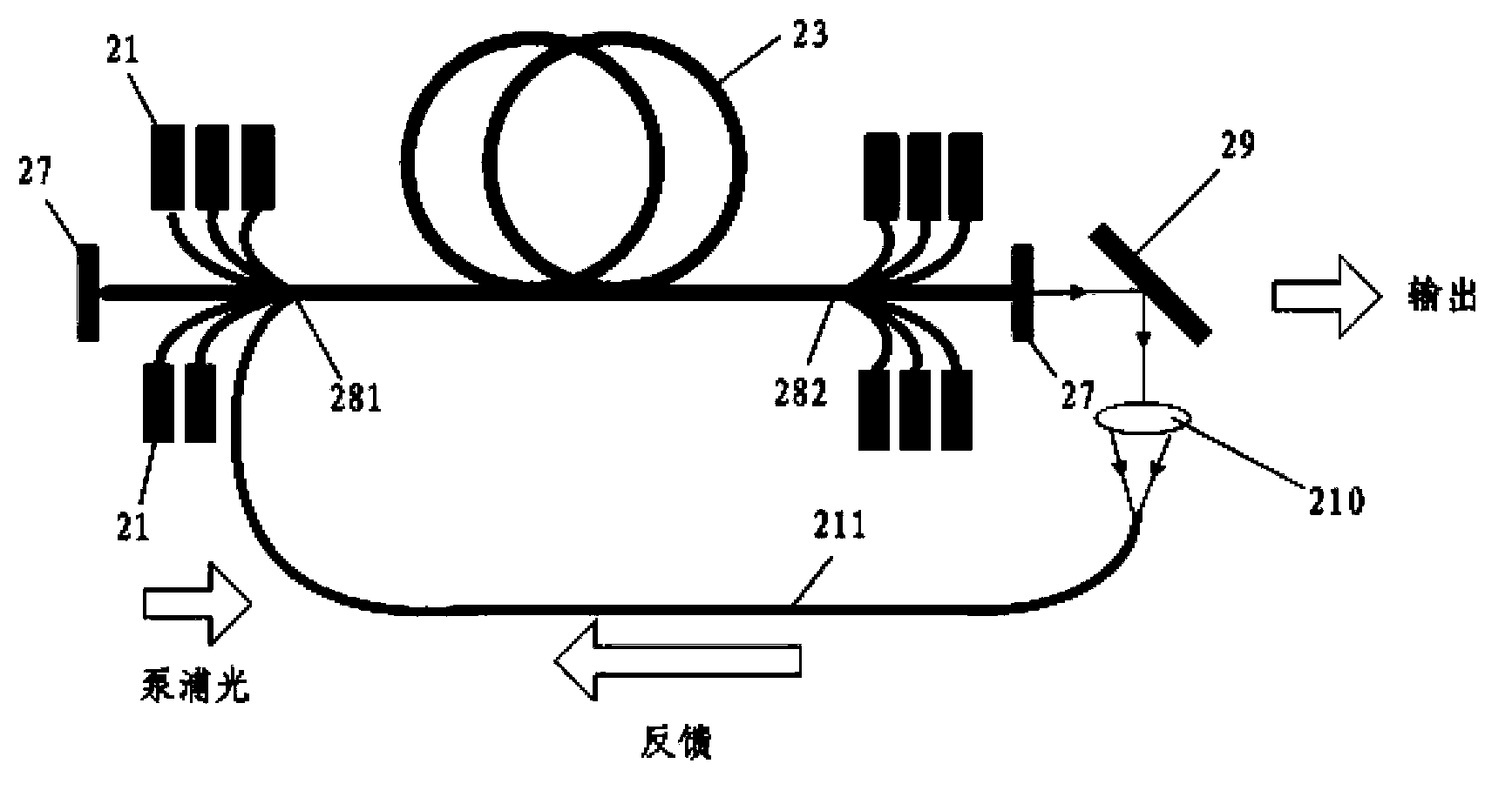
[0042] Such as figure 2 As shown, the fiber laser of this embodiment includes: a pumping device 21, a coated cavity mirror 27, a first pumping coupler 281, a second pumping coupler 282, a gain fiber 23 and a pumping feedback device, wherein:

[0043] The pump light emitted by the pump device 21 is injected into the gain fiber 23 through the first pump coupler 281 and the second pump coupler;

[0044] The coated cavity mirror 27, as a laser cavity mirror, is placed at both ends of the gain fiber 23;

[0045] The length of the gain fiber 23 is shorter than the length of the fiber required to fully absorb the injected pump light, so as to ensure 10% to 50% of the residual pump light;

[0046] The pump feedback device feeds back the residual pump light at the end of the gain fiber 23 to the pump injection end, and injects it into the gain fiber again.

[0047]The pump feedback device includes: a beam splitter 29, a coupling lens group 210 and a feedback fiber 211; after the out...


PUM


Abstract

The invention discloses an optical-fiber laser device which includes pump devices, fiber bragg gratings, a gain optical fiber and a pump feedback device. Pump light sent by the pump devices is injected into the gain optical fiber through pump couplers. The fiber bragg gratings are used as endoscopes of the laser device and fusion welded at the two ends of the gain optical fiber. The gain optical fiber is shorter in length than an optical fiber needed for completely absorption of the injected pump light so as to ensure 10%-50% of residual pump light. The pump feedback device feeds back the residual pump light at the tail end of the gain optical fiber into a pump injection end and then the pump light is injected into the gain optical fiber again. The optical-fiber laser device uses a shorter gain optical fiber to reserve specific residual pump light so that re-absorption of signal light by the gain optical fiber in the laser device is inhibited effectively and generation of a nonlinear effect is inhibited effectively and under the same output power, the laser device has a larger nonlinear effect threshold than a conventional laser device so that the laser device is applicable to laser devices of a plurality of kinds of wavelengths and amplifiers.

Description

technical field [0001] The invention relates to the field of laser technology, in particular to a fiber laser using a short gain fiber. Background technique [0002] Because of its excellent beam quality, very high power and power density, easy cooling, high stability and reliability, fiber lasers have attracted increasing attention and have been widely used in many fields. However, as the length of the gain fiber in the laser increases, problems such as nonlinear effects and signal light reabsorption gradually appear, and affect the output beam quality and output power of the laser. [0003] Generally speaking, when determining the length of the laser gain fiber, it is mainly based on the principle of fully absorbing the pump light. According to the absorption coefficient of the gain fiber for the pump light, an appropriate length is selected so that the injected pump light is almost completely absorbed. In order to ensure the high optical efficiency of the laser. However...

Claims


Application Information

Patent Timeline
Patent Type & Authority Applications(China)
IPC IPC(8): H01S3/067H01S3/091
Inventor 闫平郝金坪肖起榕巩马理张海涛
Owner TSINGHUA UNIV
Why Eureka
Try Eureka