Liquid crystal display device
A technology of liquid crystal display devices and common electrodes, applied in static indicators, nonlinear optics, instruments, etc., can solve problems such as afterimages of liquid crystal display devices, achieve the effect of improving the situation of image afterimages and improving display quality
- Summary
- Abstract
- Description
- Claims
- Application Information
AI Technical Summary
Problems solved by technology
Method used
Image

Examples
Embodiment 1
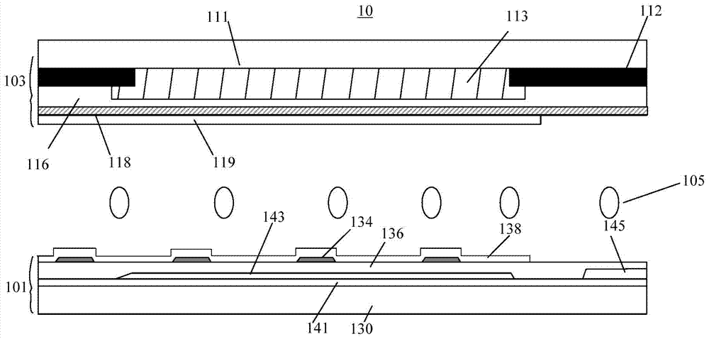
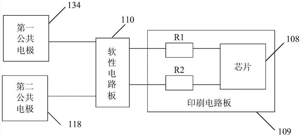
[0025] Figure 1A A schematic cross-sectional structure diagram of the liquid crystal display device 10 in the first embodiment of the present invention is shown. Figure 1B A schematic diagram of an equivalent circuit of the liquid crystal display device 10 in the first embodiment of the present invention is shown. Please refer to Figure 1A and Figure 1B The liquid crystal display device 10 includes: an array substrate 101 , a color filter substrate 103 opposite to the array substrate 101 , and a liquid crystal layer 105 located between the array substrate 101 and the color filter substrate 103 .
[0026] The array substrate 101 includes a first glass substrate 130, a plurality of scanning lines (not shown in the figure) arranged in parallel on the surface of the first glass substrate 130, the surface of the first glass substrate 130 covering the surface of the scanning lines and not covered by the scanning lines The insulating layer 141, a plurality of data lines 145 arra...
Embodiment 2
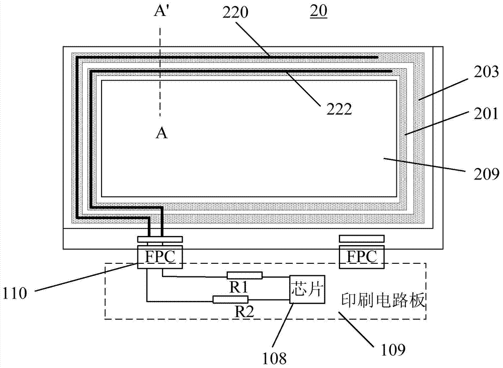
[0035] Figure 2A is a schematic top view of the liquid crystal display device in the second embodiment of the present invention; Figure 2B is along Figure 2A A schematic cross-sectional view of line A-A' in . Please also refer to Figure 2A and Figure 2B , the liquid crystal display device 20 in the second embodiment of the present invention is substantially the same as the liquid crystal display device 10 in the first embodiment of the present invention, the difference is that the liquid crystal display device 20 further includes a first seal disposed around the liquid crystal layer 105 The sealant 201 , the second sealant 203 disposed on the periphery of the first sealant 201 , the first common electrode connection line 220 and the second common electrode connection line 222 . The position of the first common electrode connection line 220 corresponds to the position of the first sealant 201 , and the position of the second common electrode connection line 222 corresp...
Embodiment 3
[0042] Figure 3A A schematic top view of the liquid crystal display device in the third embodiment of the present invention is shown. Figure 3B shows along the Figure 3A The schematic cross-sectional view of the V1-V1' line in . Figure 3C shows along the Figure 3A The cross-sectional schematic diagram of the V2-V2' line in . Figure 3D shows along the Figure 3A The schematic cross-sectional view of the liquid crystal display device along the line V3-V3' in . Please refer to Figure 3A-Figure 3D The liquid crystal display device 30 in the third embodiment of the present invention is substantially the same as the liquid crystal display device 20 in the second embodiment of the present invention, the difference is that the liquid crystal display device 30 in the third embodiment of the present invention is only provided with a sealant 301. The sealant 301 is rectangular, and is arranged on the periphery of the display area 209, between the passivation layer 336 of th...
PUM
 Abstract
Description
Claims
Application Information
 - R&D
- Intellectual Property
- Life Sciences
- Materials
- Tech Scout
- Unparalleled Data Quality
- Higher Quality Content
- 60% Fewer Hallucinations
Browse by: Latest US Patents, China's latest patents, Technical Efficacy Thesaurus, Application Domain, Technology Topic, Popular Technical Reports.
© 2025 PatSnap. All rights reserved.Legal|Privacy policy|Modern Slavery Act Transparency Statement|Sitemap|About US| Contact US: help@patsnap.com