Voice broadcast system based on visible light communication

A technology of visible light communication and voice broadcasting, applied in short-distance systems, devices providing special services in branch offices, and data exchange details, etc., can solve problems such as increasing system complexity, leakage of test questions, and damage to walls, etc. Ease of maintenance and avoidance of maintenance costs

Inactive Publication Date: 2014-07-23
SOUTHEAST UNIV
View PDF4 Cites 10 Cited by
  • Summary
  • Abstract
  • Description
  • Claims
  • Application Information

AI Technical Summary

Problems solved by technology

However, the traditional wired sound broadcasting system has the following disadvantages: First, the transmission line needs to be specially laid, and it is easy to generate parasitic capacitance to affect the system performance. problems such as gnawing, etc., increase the system maintenance cost; secondly, the wired transmission makes the speaker layout fixed and inflexible, and the sound broadcasting effect is difficult to guarantee; thirdly, the sound broadcasting of the wired transmission cannot be used in occasions with strict restrictions on electromagnetic interference; Finally, the traditional cable broadcasting system still has problems such as difficult wiring, complicated installation, poor expansion, and damage to the wall.
[0005] The wireless broadcasting system used to play listening test questions uses radio waves to transmit sound signals. It has the characteristics of no need for poles, wide coverage, unlimited expansion, convenient in...

Method used


Image

  • Voice broadcast system based on visible light communication
  • Voice broadcast system based on visible light communication
  • Voice broadcast system based on visible light communication

Examples


Embodiment Construction

[0033] The present invention will be further described below in conjunction with drawings and embodiments.

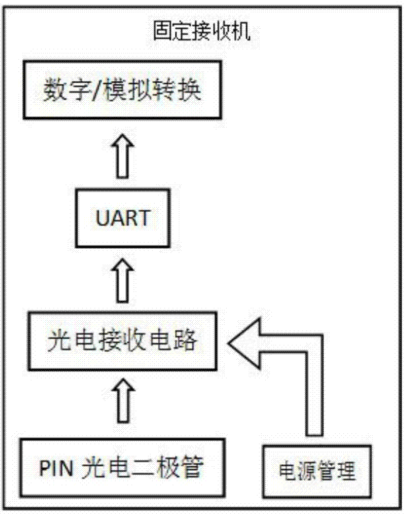
[0034] Such as figure 1 The voice broadcasting system based on visible light communication shown includes a visible light transmitter and a fixed terminal with a photodiode, and the fixed terminal is wirelessly connected to the visible light transmitter through visible light communication.

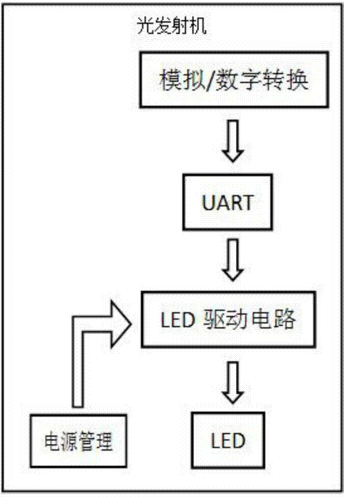
[0035] Such as figure 2 As shown, the visible light transmitter includes a power management module, an AD converter, a parallel-to-serial data conversion module, and a light-emitting diode driving circuit. Corresponding signals are connected in turn by wires between several modules.

[0036] In this case, the power management module can use an AC-DC conversion circuit to convert 220V AC power into government 15V DC power.

[0037] In this case, the parallel-to-serial data conversion module uses FPGA to realize UART universal asynchronous serial transmission.

[0038] Such as ...


PUM


Abstract

The invention discloses a voice broadcast system based on visible light communication. The voice broadcast system based on the visible light communication comprises a visible light emitter and a fixed terminal comprising a photodiode, wherein the fixed terminal is connected with the visible light emitter in a wireless visible light communication mode; the visible light emitter comprises an AD (analog/digital) converter, a parallel-series data conversion module, an LED (light emitting diode) and an LED driving circuit, and the parallel-series data conversion module comprising a first FPGA (field programmable gate array) processer; the fixed terminal comprises a photoelectric receiver, a parallel-series data conversion module, a DA (data/analog) converter and a loudspeaker box and the parallel-series data conversion module comprises a second FPGA processor. The voice broadcast system based on the visible light communication achieves a voice signal wireless communication function through lighting visible light, can be applied to voice information broadcasting in places requiring all-weather lighting such as superstores and subway stations as well as radio broadcasting in places requiring secure communication such as examination rooms, and is convenient to mount and maintain, wide in usage range, energy-saving, environmentally friendly, scientific, reasonable, safe and reliable.

Description

technical field [0001] The invention relates to a voice broadcast system based on visible light communication, which belongs to the field of multimedia information transmission and playback. Background technique [0002] In recent years, semiconductor (LED) lighting technology known as "green lighting" has developed rapidly, especially white LEDs are attracting more people's attention, and they are considered to be the next generation of lighting sources. It will eventually replace incandescent and fluorescent light bulbs that are widely used in offices and homes today. Utilizing the high-speed light-emitting response characteristics of LEDs, the signal is modulated to the visible light of LEDs for transmission, which can realize the high-efficiency mode of lighting and communication integration. [0003] Sound broadcasting is usually used in stations, shopping malls, public venues, buildings, and residential areas for background music broadcasting, paging broadcasting, and...

Claims


Application Information

Patent Timeline
IPC IPC(8): H04B10/116H04L12/18
Inventor 翟邦昭张建飞梁霄
Owner SOUTHEAST UNIV
Why Eureka
Try Eureka