Hydrogen catalytic burner

A catalytic burner, hydrogen technology, applied to gas fuel burners, burners, combustion methods, etc., can solve problems such as danger, hydrogen loss, and reduced combustion efficiency, and achieve high catalytic combustion efficiency, low "leakage" probability, The effect of simple structure

Inactive Publication Date: 2014-07-30
CHINA JILIANG UNIV
View PDF7 Cites 11 Cited by
  • Summary
  • Abstract
  • Description
  • Claims
  • Application Information

AI Technical Summary

Problems solved by technology

In the actual application process, due to the improper design of the gas circuit in some existing hydrogen catalytic burners, the hydrogen / air mixture often cannot be effectively contacted with the catalyst, and most of the hydrogen will be lost from the fast channel, which greatly reduces the combustion efficiency. In severe cases, it will also bring danger due to the high concentration of hydrogen gas at the tail gas end

Method used


Image

  • Hydrogen catalytic burner

Examples


Embodiment 1

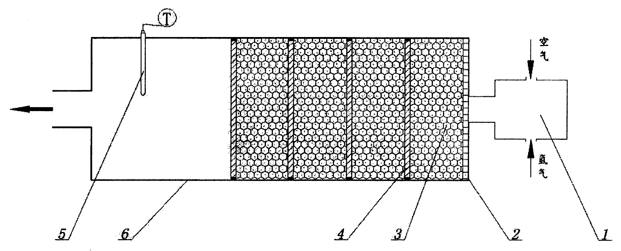
[0019] A hydrogen catalytic burner is provided with a hydrogen / air gas mixing chamber 1 and a porous liner 2, and the porous liner 2 is placed at the bottom of the hydrogen catalytic burner. The catalyst layer 3 has a multi-layer structure, and separators 4 are arranged between the catalyst layers, and the separators 4 are flanged porous separators. The separator 4 is sealed with the wall of the hydrogen catalytic burner 6 through interference fit. The hydrogen / air mixture from the gas mixing chamber 1 enters the first catalyst layer 3 through the porous liner 2 , and then enters the second catalyst layer through the holes on the separator 4 . Since the partition 4 is tightly sealed with the wall of the hydrogen catalytic burner 6 , the hydrogen / air mixture will not pass through the wall of the burner 6 .

[0020] There are three catalyst layers, the catalyst layer is ceramic powder loaded with precious metals, and the catalyst carrier is γ-Al 2 o 3 The ceramic powder, the ...

Embodiment 2

[0022] A hydrogen catalytic burner is provided with a gas mixing chamber, a porous liner, a catalyst layer, a partition and a temperature sensor. The porous liner is placed at the bottom of the hydrogen catalytic burner, the catalyst layers are multi-layered, and partitions are arranged between the catalyst layers. The partition is a flanged porous aluminum alloy plate, and the partition is sealed with the wall of the catalytic burner through interference fit.

[0023] There are six catalyst layers in total, and the catalyst layer is a glass fiber mat loaded with precious metals. The catalyst carrier is glass fiber felt, the catalyst is noble metal ruthenium, and the catalyst load is 1% of the carrier mass. When the hydrogen / air mixture with a fuel-air ratio of 1 / 25 passes through the catalytic burner, hot air at 280°C (measured temperature) is obtained, and the hydrogen concentration in the tail gas is less than 10PPM.

Embodiment 3

[0025] A hydrogen catalytic burner is provided with a gas mixing chamber, a porous liner, a catalyst layer, a partition and a temperature sensor. The porous liner is placed at the bottom of the hydrogen catalytic burner, the catalyst layer has a multi-layer structure, and partitions are arranged between the catalyst layers. The partition is a flanging porous red copper plate, and the partition is sealed with the wall of the catalytic burner through interference fit.

[0026] There are six catalyst layers in total, and the catalyst layer is a glass fiber mat loaded with precious metals. The catalyst carrier is a glass fiber mat, the catalyst is three composites of Pd, Pt and Ru, and the catalyst load is 0.8% of the carrier mass. When the hydrogen / air mixture with a fuel-air ratio of 1 / 25 passes through the catalytic burner, hot air at 280°C (measured temperature) is obtained, and the hydrogen concentration in the tail gas is less than 5PPM.

[0027] This embodiment has the ad...


PUM


Abstract

The invention relates to a hydrogen catalytic burner, and belongs to the technical field of hydrogen catalytic combustion. The hydrogen catalytic burner is characterized by comprising a gas nixing cavity, a porous lining plate, catalyst layers, baffles, and a temperature sensor, wherein the porous lining plate is arranged at the bottom of the hydrogen catalytic burner, and the catalyst layer is a multilayer structure; the baffles are arranged between the catalyst layers. The hydrogen catalytic burner provided by the invention has the advantages of simple structure, good catalytic effect, convenience in use, high catalytic combustion efficiency, low emission and the like, and is particularly suitable for use for warming homes and office places.

Description

technical field [0001] The invention belongs to the technical field of hydrogen catalytic combustion, in particular to a hydrogen catalytic burner. Background technique [0002] The history of human energy development has developed from the age of firewood and coal to the current oil age, and has reached the peak of pressure on resources and the environment. Energy conservation and development of renewable energy have become an inevitable requirement for sustainable economic development. Hydrogen is An energy carrier that can be directly burned to generate heat for residential heating, or generated by fuel cells (FC) or hydrogen internal combustion engines (ICEs) for residential lighting or driving cars. The utilization of hydrogen energy does not produce greenhouse gases, and it is a clean energy source. When combined with renewable energy sources such as wind energy and solar energy, there is no problem of resource depletion. Therefore, it is considered to be a solution to...

Claims


Application Information

Patent Timeline
Patent Type & Authority Applications(China)
IPC IPC(8): F23D14/18
Inventor 黄岳祥钮峰孙杏国
Owner CHINA JILIANG UNIV
Why Eureka
Try Eureka