Automatic manufacturing device of flange plate

A technology for manufacturing devices and active power, applied in manufacturing tools, other manufacturing equipment/tools, metal processing, etc., can solve the problems of high logistics cost, high labor intensity, long process flow, etc., to save investment in plant construction and reduce equipment Quantity, the effect of reducing the number of workers

Active Publication Date: 2014-08-06
BEIJING WELLTECH CNC EQUIP
View PDF7 Cites 2 Cited by
  • Summary
  • Abstract
  • Description
  • Claims
  • Application Information

AI Technical Summary

Problems solved by technology

[0016] 1 The labor intensity is high, which makes workers prone to lumbar muscle strain, lumbar disc herniation and other diseases, and the workers' willingness to work is low;
[0017] 2 The number of operators is large and the labor cost is high;
[0018] 3 The number of equ

Method used


Image

  • Automatic manufacturing device of flange plate
  • Automatic manufacturing device of flange plate
  • Automatic manufacturing device of flange plate

Examples


Embodiment 1

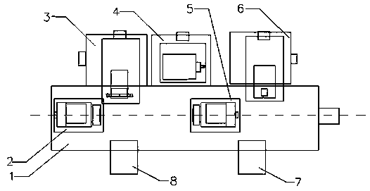
[0055] Such as figure 1 As shown, an automatic manufacturing device for a flange includes a main bed unit 1, a first turning power unit 2, a turning feed unit 3, a drilling unit 4, a second turning power unit 5, a marking unit 6, a lower Material unit 7, material loading unit 8 and control system.

[0056]The first turning power unit 2 and the second turning power unit 5 are arranged on the same straight line of the main bed unit 1, the first turning power unit 2 is fixed on one end of the main bed unit 1, and the second turning power unit 5 can be moved along The straight line slides on the guide rail on the main bed unit 1, the turning feed unit 3, the drilling unit 4 and the marking unit 6 are sequentially arranged on the side of the main bed unit 1, and the feeding unit 8 and the unloading unit 7 are arranged on the The other side of the main bed unit. The first turning power unit 2 receives the workpiece to be processed (from the feeding unit 8) and provides the active ...

Embodiment 2

[0066] In this embodiment, the marking unit 6 and the feeding unit 8 can be simplified to form a simplified version of the flange manufacturing station to complete all mechanical processing. The simplified version of the flange manufacturing station manually loads the workpiece to reduce costs. The flange plate manufacturing station without the identification unit 6 is beneficial to reduce the complexity of the control system.


PUM


Abstract

The invention provides an automatic manufacturing device of a flange plate. The automatic manufacturing device comprises a main lathe bed unit, a first turning power unit, a turning feeding unit, a drilling unit, a second turning power unit, a discharging unit and a control system. The first turning power unit receives a workpiece to be machined and provides main power for a first turning portion, the turning feeding unit is provided with a turning tool, the first turning power unit is controlled by the control system to drive the workpiece to be machined to complete the first turning portion under the action of the turning feeding unit, the second turning power unit provides main power for a second turning portion, the second turning power unit drives the workpiece to be machined to move, the second turning portion is complete, the drilling work on the workpiece to be machined is completed under the action of the drilling unit, and discharging and workpiece collecting work are completed under the action of the discharging unit. The device is achieved on the basis of the digital control automation integration technology, and all mechanical cutting machining and lettering marking of the flange plate can be completed on one device.

Description


Claims


Application Information

Patent Timeline
Owner BEIJING WELLTECH CNC EQUIP
Why Eureka
Try Eureka