Centrifugal vacuum pump

A vacuum pump and centrifugal technology, which is applied in the field of centrifugal vacuum pumps, can solve problems such as shortening the service life of vacuum pumps, pump wheel spots and cracks, and noise, and achieve significant economic benefits, low water consumption, and low supporting power.

Active Publication Date: 2014-08-06
WUHAN WU PUMP PUMP MFG
View PDF4 Cites 10 Cited by
  • Summary
  • Abstract
  • Description
  • Claims
  • Application Information

AI Technical Summary

Problems solved by technology

However, the cost is high. When the vacuum requirement of the condenser reaches a high vacuum of 4.9kPa during operation, high-intensity shock waves are generated due to the high-speed operation of the pump wheel, which impacts the pump wheel and the pump casing, causing noise and vibration, and cavitation. Spots and cracks appear on the surface of the pump wheel and even cause spongy damage, which drastically shortens the service life of the vacuum pump

Method used


Image

  • Centrifugal vacuum pump
  • Centrifugal vacuum pump
  • Centrifugal vacuum pump

Examples


Embodiment Construction

[0022] In order to make the object, technical solution and advantages of the present invention clearer, the present invention will be described in further detail below in conjunction with specific embodiments and with reference to the accompanying drawings.

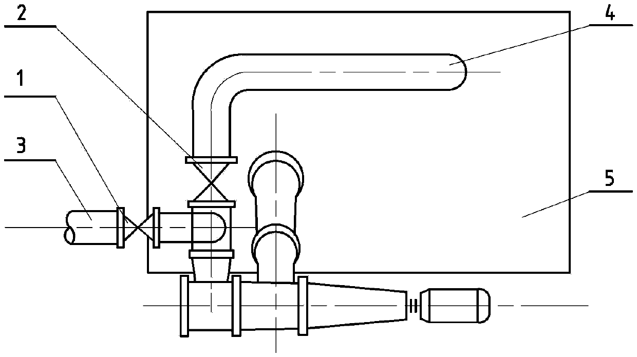
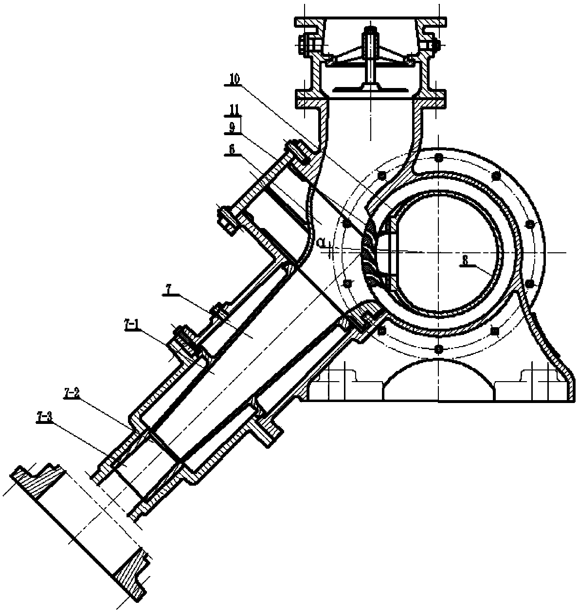
[0023] figure 1 It is a schematic diagram of the working water system of the centrifugal vacuum pump of the present invention. Such as figure 1 As shown, wherein 1 is a pressure water inlet valve, 2 is a siphon valve, 3 is a pressure water pipe, 4 is a siphon water inlet pipe, and 5 is a water chamber. Before the centrifugal vacuum pump is started, there is no vacuum in the space of the mixing chamber 6, and water cannot enter the water chamber 5 and the square guide vane 10 by siphon effect, and the centrifugal vacuum pump cannot work normally. Therefore, the centrifugal vacuum pump needs to rely on The low-pressure water flows from the pressure water pipe 3 through the scimitar-shaped impeller 9 to slowly create a low...


PUM


Abstract

The invention discloses a centrifugal vacuum pump. The vacuum pump is a hydraulic partial spraying turbine driven by a motor. Water enters a water chamber and a square guide vane by depending on the pressure difference between the water surface of the water chamber and the vacuum in a mixing chamber under the siphoning action of a siphoning water inlet pipe, then enters a rotating vane wheel after passing through a vane wheel distributor, and finally is jetted at a high speed; the air in a condenser is carried away by the high-speed water flow to form the vacuum, the water-air mixture is contracted and expanded in a spraying pipe, the water flows into the water chamber, and the air is exhausted into the atmosphere. The centrifugal vacuum pump is suitable for air exhaust, condensation, crystallization and the like, and can be applied to industries such as electric power, chemical industry, pharmacy, environmental protection and metallurgy.

Description

technical field [0001] The invention relates to the field of power plant exhaust equipment, in particular to a centrifugal vacuum pump. Background technique [0002] The condensing steam turbine is a typical steam turbine widely used in modern thermal power plants and nuclear power plants, and the condensing equipment is an important part of the condensing unit. Therefore, the performance of the condensing equipment directly affects the thermal economy of the entire unit. sex and safety. As an important part of the condensing equipment, the extraction equipment plays an important role. [0003] During the working process of the condensing equipment, the air extraction equipment continuously extracts the air leaked into the condenser to prevent the accumulation of non-condensable gas in the condenser, increase the pressure in the condenser, and maintain the condenser At the same time, ensure that the heater has a high heat exchange efficiency; timely extract the non-condens...

Claims


Application Information

Patent Timeline
Patent Type & Authority Applications(China)
IPC IPC(8): F04D17/10F04D17/18
Inventor 张怀明张黎
Owner WUHAN WU PUMP PUMP MFG
Why Eureka
Try Eureka