High-temperature energy-saving furnace

An energy-saving furnace and high-temperature technology, which is applied in the direction of household furnace/stove, household heating, heating fuel, etc., can solve the problems of high gas consumption, fuel loss, high degree of environmental pollution, etc., and achieve high combustion temperature, simple structure and low price. cheap effect

Inactive Publication Date: 2014-08-06
康智文
View PDF13 Cites 2 Cited by
  • Summary
  • Abstract
  • Description
  • Claims
  • Application Information

AI Technical Summary

Problems solved by technology

Because the combustion system of the existing fan-type stove is not scientific enough, the gas and fuel are not fully utilized, resulting in a large amount of fuel being lost to the air before being fully burned, resulting in a large amount of energy waste and a large amount of waste gas. Toxic gases such as carbon monoxide are harmful to the human body. Therefore, the

Method used


Image

  • High-temperature energy-saving furnace
  • High-temperature energy-saving furnace
  • High-temperature energy-saving furnace

Examples


Embodiment 1

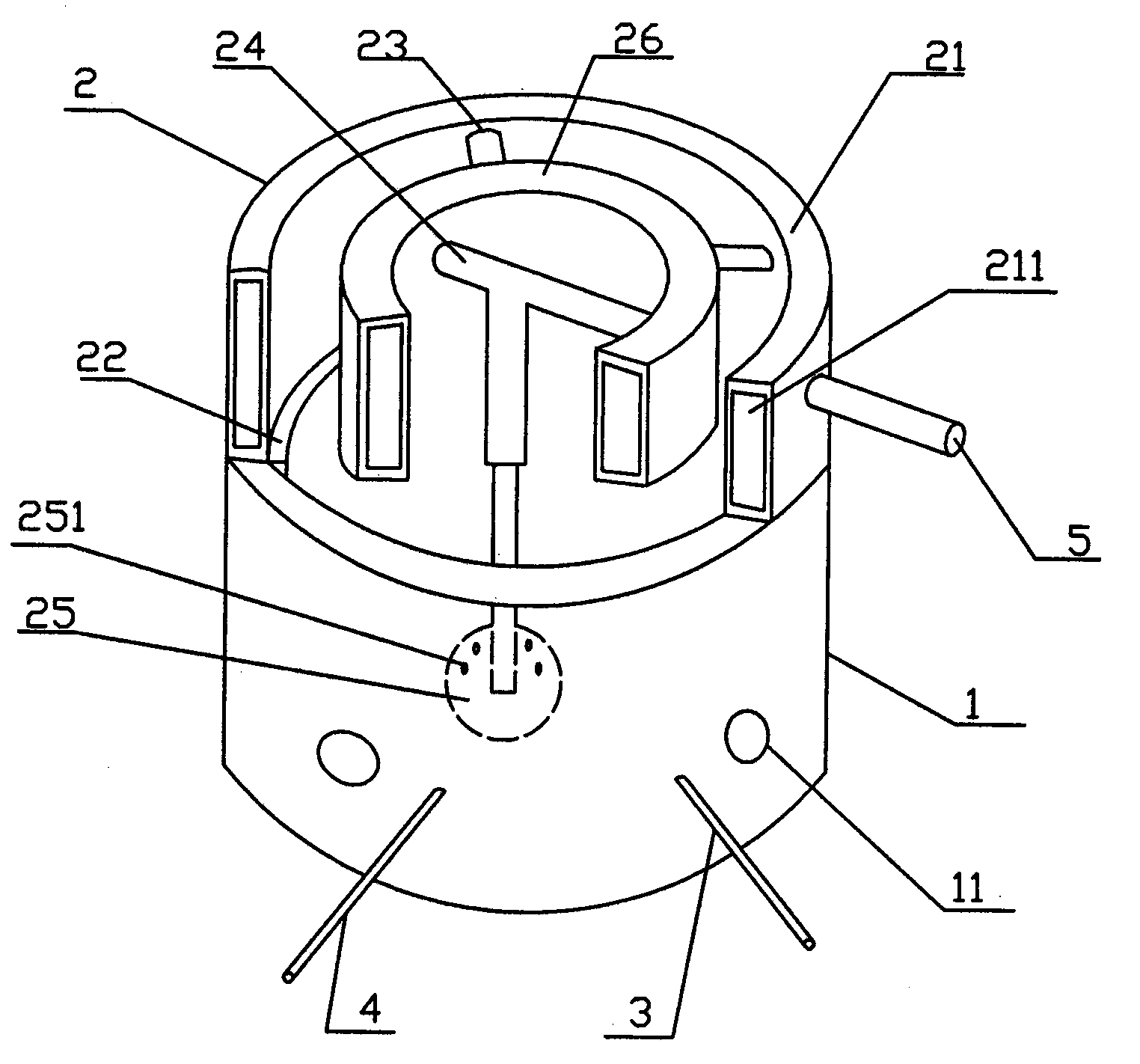
[0019] Such as figure 1 Shown, a kind of high-temperature energy-saving furnace, it comprises furnace base 1, furnace gall 2, ignition device 3, ignition oil inlet pipe 4, oil delivery pipe 5, furnace base 1 is a hollow cylindrical body, furnace base 1 wall body is provided with several Air vent 11, ignition device 3 and ignition oil inlet pipe 4 are installed on the wall body of furnace base 1 respectively, and the igniter of ignition device 3 and the oil outlet of oil inlet pipe 4 are arranged in furnace base 1, and igniter can be on the oil inlet pipe The oil liquid sprayed at the oil outlet is ignited; the furnace bladder 2 includes an outer bladder 21, a bladder seat 22, a fuel pipe 23, a three-way pipeline 24, a vaporization spheroid 25 and an inner tank 26, and the outer tank 21 and the inner tank 22 are both The annular interior is provided with the bile-shaped body of the hollow oil delivery chamber 211, and the diameter of the inner container is smaller than the diam...

Embodiment 2

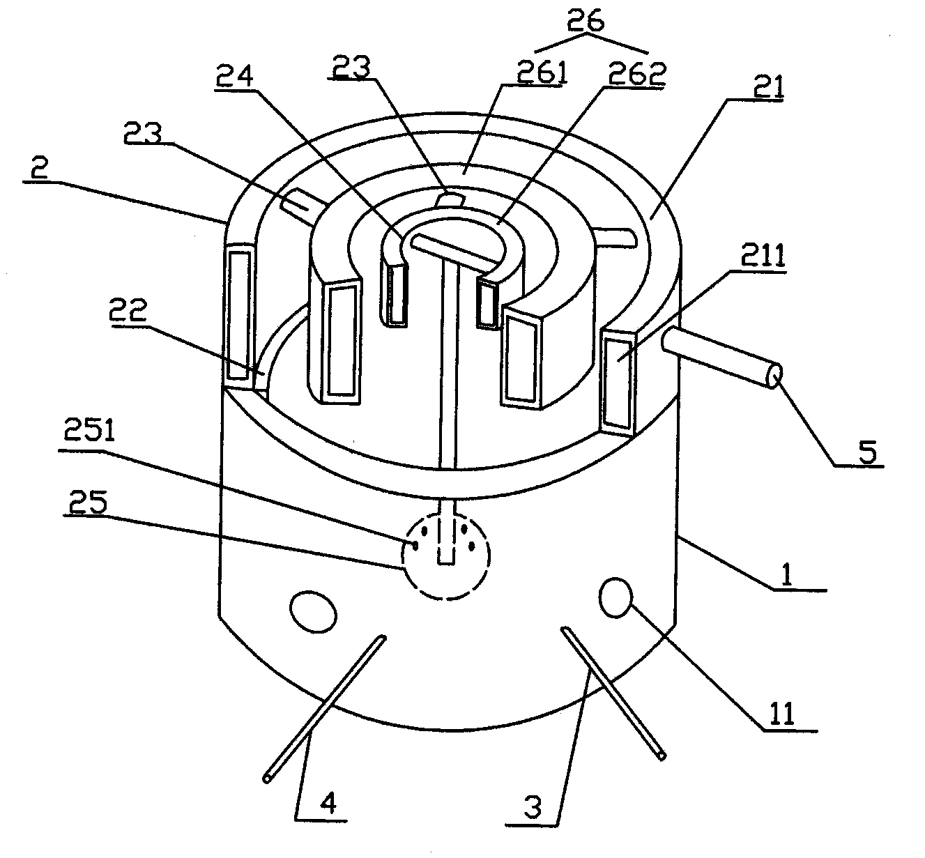
[0021] Such as figure 2 Shown, a kind of high-temperature energy-saving furnace, it comprises furnace base 1, furnace gall 2, ignition device 3, ignition oil inlet pipe 4, oil delivery pipe 5, furnace base 1 is a hollow cylindrical body, furnace base 1 wall body is provided with several Air vent 11, ignition device 3 and ignition oil inlet pipe 4 are installed on the wall body of furnace base 1 respectively, and the igniter of ignition device 3 and the oil outlet of oil inlet pipe 4 are arranged in furnace base 1, and igniter can be on the oil inlet pipe The oil liquid sprayed at the oil outlet is ignited; the furnace bladder 2 includes an outer bladder 21, a bladder seat 22, a fuel pipe 23, a three-way pipeline 24, a vaporization spheroid 25 and two inner tanks 26, and the outer tank 21 and the inner tank 22 are all It is a bile-shaped body with a hollow oil delivery chamber 211 inside the ring shape, and the diameter of the inner pot is smaller than that of the outer pot. T...


PUM


Abstract

The invention discloses a high-temperature energy-saving furnace comprising an igniter arranged on a furnace base, an ignition oil inlet and a furnace pipe which is buckled on the furnace base and communicated with an oil delivery pipeline, wherein the furnace pipe comprises an outer pipe, a pipe base, fuel pipes, a three-way pipeline, an evaporation ball body and at least one inner pipe; the pipe base is fixedly arranged at the bottom of the outer pipe; the oil delivery pipeline is communicated with the outer pipe; the outer pipe and each inner pipe as well as the inner pipes are communicated through the fuel pipes, tapered in diameter and coaxially arranged; the three-way pipeline is respectively communicated with the inner pipes and an inner oil delivery cavity of the evaporation ball body at the bottoms of the inner pipes; the upper part of the evaporation ball body is provided with multiple oil spit holes. According to the furnace, liquid fuel is converted into gas fuel through cyclic gasification of the furnace pipe, the fuel molecular formula effect of the liquid fuel is changed, the use ratio of the gas fuel is increased by 30-40% when being compared with that of existing fuel, the pressure of the fuel is improved and then the combustion temperature is increased accordingly, no smoke, smell and carbon deposition residue exist in the combustion process, the full utilization of resources is realized, and the low-carbon, energy-saving and environment-friendly effects are realized.

Description

technical field [0001] The invention relates to the field of furnaces, in particular to a high-temperature energy-saving furnace. Background technique [0002] Most of the existing stoves are fan-type stoves, the main principle of which is to use the fan to continuously blow the oil to atomize the oil, and then ignite the oil mist in the stove. Because the combustion system of the existing fan-type stove is not scientific enough, the gas and fuel are not fully utilized, resulting in a large amount of fuel being lost to the air before being fully burned, resulting in a large amount of energy waste and a large amount of waste gas. Toxic gases such as carbon monoxide are harmful to the human body. Therefore, the existing fan-type stoves generally have the disadvantages of large power consumption, large gas consumption, large emissions of harmful gases, and high levels of environmental pollution. In today's society where energy is scarce Under the current situation, it is urgen...

Claims


Application Information

Patent Timeline
IPC IPC(8): F24C5/02F24C15/00
Inventor 康智文
Owner 康智文
Why Eureka
Try Eureka