
Hearth direct-combustion energy-saving hot-shear furnace

A hot shearing furnace and hearth technology, applied in the field of furnace direct-fired energy-saving thermal shearing furnace, can solve the problems of high exhaust gas temperature, waste of energy, waste of gas, etc., and achieve the goal of reducing the volume of the furnace, improving product quality, and reducing gas consumption Effect

Inactive Publication Date: 2014-08-06
荣咨海
View PDF9 Cites 4 Cited by
  • Summary
  • Abstract
  • Description
  • Claims
  • Application Information

AI Technical Summary

Problems solved by technology

The second is that the combustion flame and the circulating air lose a lot of heat in the heat exchange process
[0004] 2. The exhaust gas temperature is high, reaching above 320°C, which wastes energy
[0005] 3. The temperature difference in the furnace is large, and the aluminum rod is heated in the furnace. It is generally divided into three areas. Due to the suction effect of the circulating fan, the temperature in the II area is 30°C lower than that of the I and III areas, or even as high as 70°C. Lost extrusion quality, wasted energy
[0006] 4. The control method of air-fuel ratio is too simple to precisely organize combustion, CO reaches 1200ppm, O 2 The content reaches 16%, the loss of chemical incomplete combustion is large, the amount of smoke is large, and the loss of smoke exhaust is high
[0007] 5. The hearth is too large and there are too many rods. Nowadays, multi-rod furnaces generally contain 12 rods, which store a large amount of heat and waste gas after repeated heating and cooling.

Method used


Image

  • Hearth direct-combustion energy-saving hot-shear furnace
  • Hearth direct-combustion energy-saving hot-shear furnace
  • Hearth direct-combustion energy-saving hot-shear furnace

Examples


Embodiment Construction

[0023] The present invention will be described in detail below in conjunction with the accompanying drawings and embodiments.

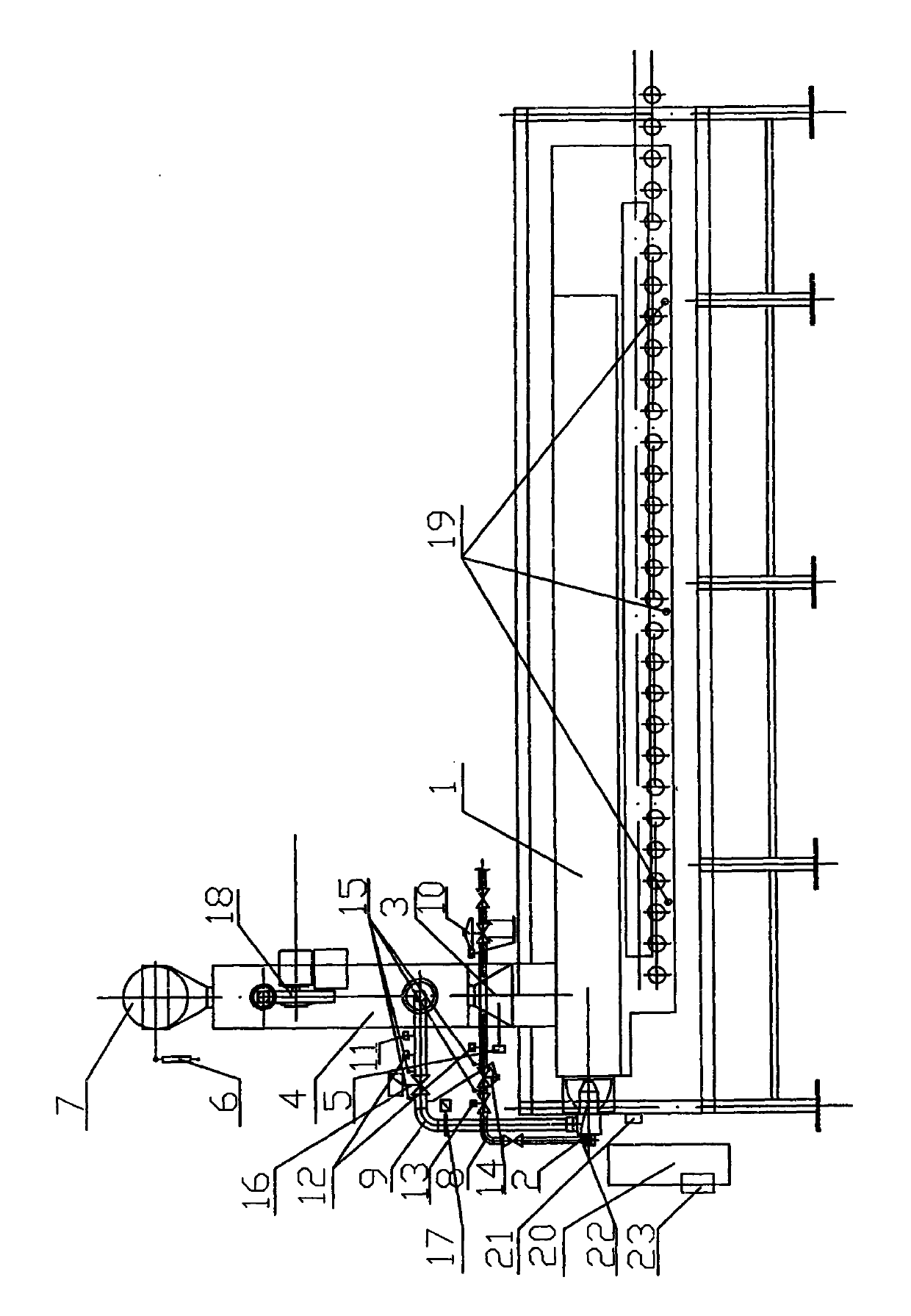
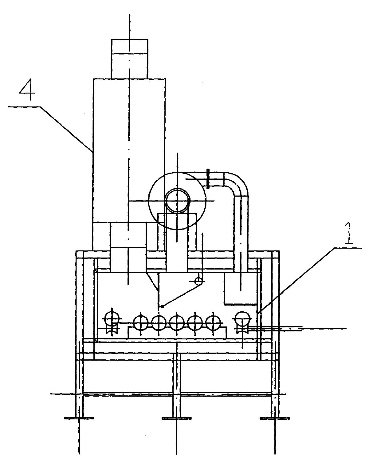
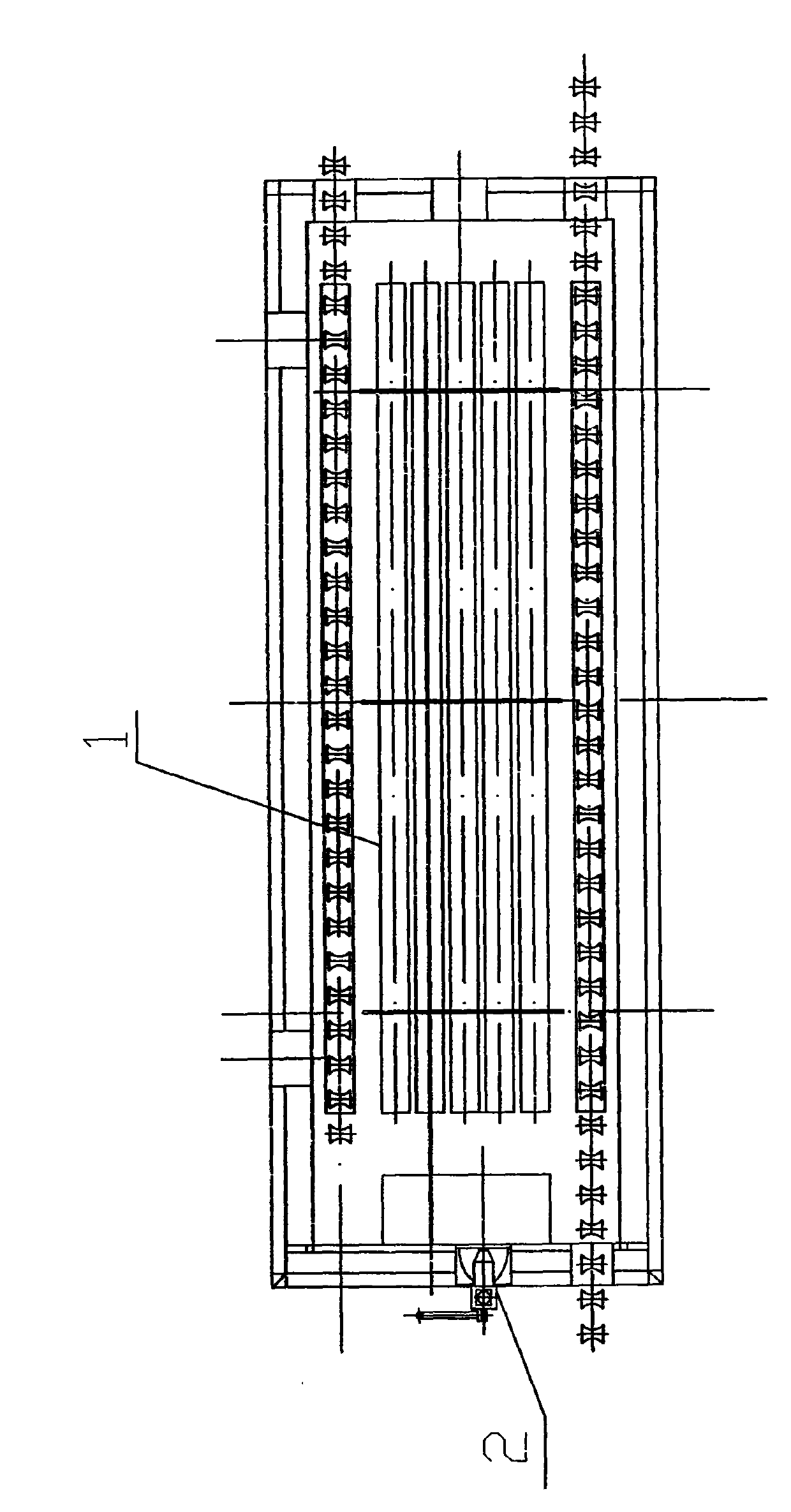
[0024] Such as figure 1 As shown, it is a kind of hearth direct-fired energy-saving thermal shearing furnace of the present invention, is provided with a hearth 1, is provided with a high-speed burner 2 on the wall of described hearth 1 bar outlet side, and described hearth 1 top is provided with flue 3, so A plate heat exchanger 4 is installed on one side of the flue 3 to recover the waste heat of the flue gas. A zirconia oxygen content measuring instrument 5 is arranged in the flue 3 , and a pneumatic cylinder 6 and a flue baffle 7 are arranged on the top of the flue 3 .

[0025] In order to reduce resistance, a combustion-supporting fan 18 is also provided in the middle of the plate heat exchanger 4, and the combustion-supporting fan 18 sends the combustion-supporting air into the plate heat exchanger 4 to exchange heat with the flue gas, reducing...


PUM


Abstract

The invention discloses a hearth direct-combustion energy-saving hot-shear furnace which comprises a hearth and a PLC (Programmable Logic controller) control system, wherein a high-speed combustor is arranged on a wall of a hearth discharge rod; the high-speed combustor is connected with the PLC control system through a circuit; a flue is arranged at the upper part of the hearth; a plate type heat exchanger for recycling a fume rest heat is mounted on one side of the flue; the flue is internally provided with a zirconium oxide content tester; a pneumatic cylinder and a flue baffle are arranged at the top of the flue. The hearth direct-combustion energy-saving hot-shear furnace can precisely organize combustion and recycle the rest heat of fume; when the combustor is changed into the high-speed combustor which is directly mounted inside the hearth, a gas inside the hearth is stirred by high-speed air flow of 150m / s generated from the high-speed combustor, the temperature inside the hearth is uniform, the number of aluminum rods is reduced by 7-9, the capacity of the hearth is reduced, the volumetric heat intensity of the heart is improved. The purposes of improving the product quality, reducing fuel consumption and reducing pollution are achieved.

Description

technical field [0001] The invention relates to a heating furnace, in particular to a furnace direct-fired energy-saving thermal shearing furnace. Background technique [0002] At present, there are generally three types of aluminum rod heating furnaces in the extrusion process of the aluminum profile industry, namely single rod furnaces, short rod furnaces and multi rod furnaces. Among them, the multi-rod furnace not only heats the aluminum rods to meet the extrusion requirements, but also has the function of homogenizing the aluminum rods. The multi-rod furnace currently used has the following disadvantages: [0003] 1. Set up a combustion chamber separately, and use the circulating fan to bring heat into the furnace to heat the aluminum rod. There are two problems in this process. One is that the combustion of the burner is intermittent. After the temperature reaches the set temperature, the burner is turned off. When the temperature is lower than the set temperature, t...

Claims


Application Information

Patent Timeline
Patent Type & Authority Applications(China)
IPC IPC(8): F27B17/00F27D17/00F27D19/00F27D21/00C22F1/04
Inventor 荣咨海
Owner 荣咨海
Learn More