Vortex optical fiber on basis of linear refractive index distribution and preparation method thereof
A technology of refractive index distribution and refractive index, which is applied in the direction of cladding optical fiber, glass manufacturing equipment, manufacturing tools, etc., can solve the problem of destroying the orbital angular momentum mode, etc., and achieve the effect of simple preparation and good space flexibility
- Summary
- Abstract
- Description
- Claims
- Application Information
AI Technical Summary
Problems solved by technology
Method used
Image
Examples
preparation example Construction
[0023] The preparation process of the optical fiber can be divided into the following steps (such as Figure 5-Figure 6 ):
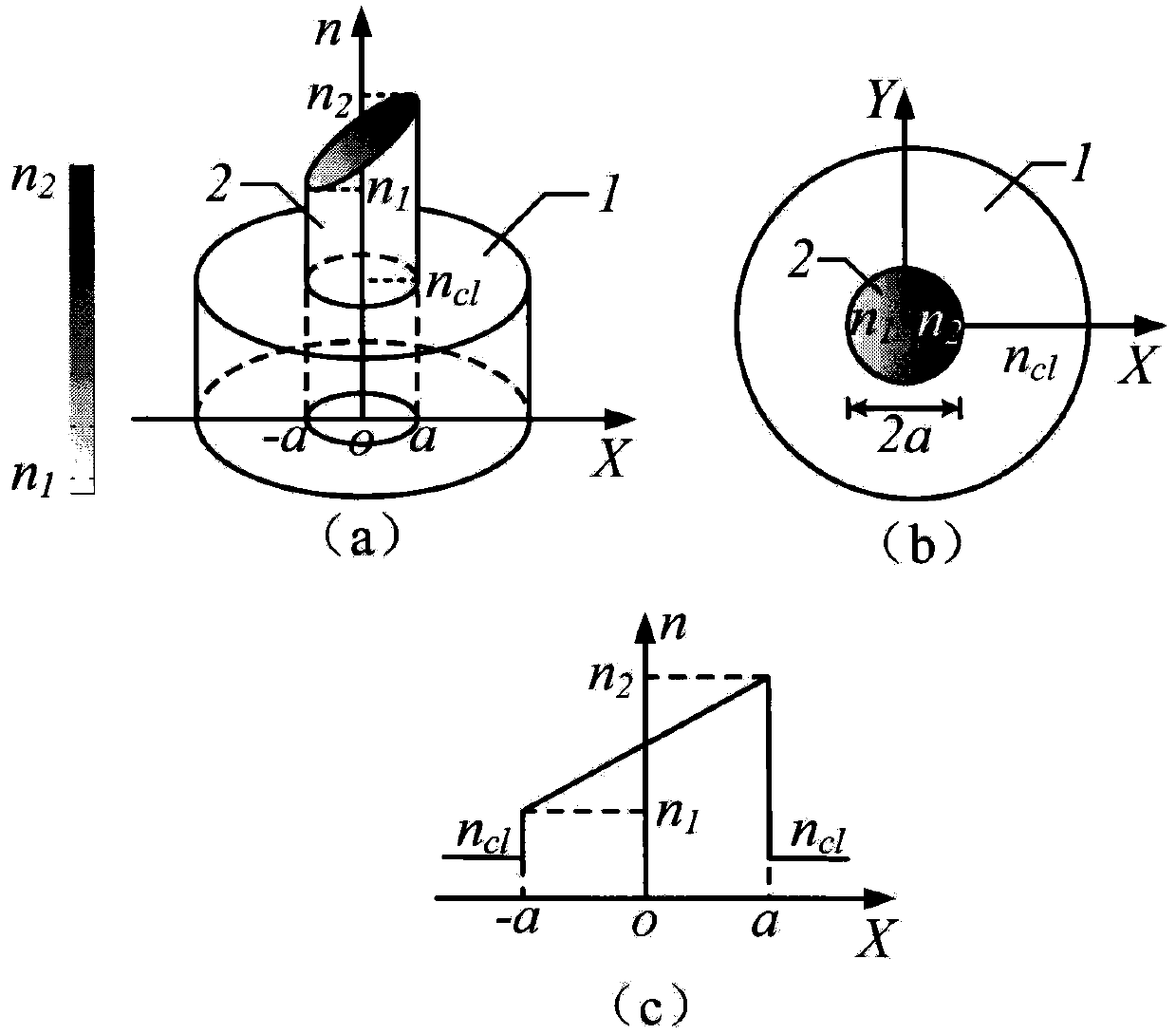
[0024] Step 1: If Figure 5 As shown, a section of polarization-maintaining fiber 6 is selected, and the refractive index distribution of the fiber cladding 7 is a constant constant n cl , while the refractive index of the core 8 has a linear distribution (the minimum value is n 1 , with a maximum value of n 2 );
[0025] Step 2: If Figure 6 As shown, one end of the polarization-maintaining optical fiber 6 is fixed with an optical fiber clamp 9, and a vertical load 10 is applied to the other end to keep the polarization-maintaining optical fiber 6 in a vertical state;
[0026] Step 3: heating the fixed polarization-maintaining optical fiber 6, and applying an axial torsional force 12 when the optical fiber in the heated area 11 is in a molten state;
[0027] Step 4: stop heating, and obtain the vortex optical fiber 13 after the optical fiber in th...
Embodiment 1
[0030] 1. Optical fiber preparation: the vortex optical fiber 13 is prepared according to the optical fiber preparation method of the first embodiment;
[0031] 2. Light source coupling: cut the prepared vortex optical fiber 13, and then align and weld it with the single-mode optical fiber 15 with the light source pigtail, such as Figure 8 shown;
[0032] 3. Generation of vortex beam: After inputting laser light 16, vortex optical mode transmission will be realized in vortex optical fiber 13, and a quasi-vortex beam can be output at the fiber end.
Embodiment 2
[0034] The vortex optical fiber 13 in embodiment 1 can be replaced by the vortex optical fiber 17 that the pitch of the refractive index distribution helical curve changes, as Figure 9 .
PUM
 Abstract
Description
Claims
Application Information
 - R&D
- Intellectual Property
- Life Sciences
- Materials
- Tech Scout
- Unparalleled Data Quality
- Higher Quality Content
- 60% Fewer Hallucinations
Browse by: Latest US Patents, China's latest patents, Technical Efficacy Thesaurus, Application Domain, Technology Topic, Popular Technical Reports.
© 2025 PatSnap. All rights reserved.Legal|Privacy policy|Modern Slavery Act Transparency Statement|Sitemap|About US| Contact US: help@patsnap.com


