
Wave length demodulating device based on integrated optical waveguide coupler

An integrated optical waveguide and wavelength demodulation technology, which is applied in the direction of transmitting sensing components, light guides, instruments, etc. by optical devices, can solve problems such as poor reliability and stability, complex system structure, and degradation of demodulation accuracy, and achieve stability Excellent, good anti-disturbance performance, simple structure

Active Publication Date: 2014-08-20
HUAZHONG UNIV OF SCI & TECH
View PDF9 Cites 0 Cited by
  • Summary
  • Abstract
  • Description
  • Claims
  • Application Information

AI Technical Summary

Problems solved by technology

But they have the following problems: (1) the system structure is complicated and the cost is high
(2) The reliability and stability of the device are poor, and the practicability is not high
For the scheme of introducing tunable devices, the tunable part will inevitably bring unstable factors (such as the aging of piezoelectric devices, thermal stability of thermoelectric devices, etc.). Optical path, CCD, etc.) requires precise positioning and alignment. For the fiber coupler solution, the polarization state change caused by fiber perturbation will lead to the degradation of demodulation accuracy

Method used


Image

  • Wave length demodulating device based on integrated optical waveguide coupler
  • Wave length demodulating device based on integrated optical waveguide coupler
  • Wave length demodulating device based on integrated optical waveguide coupler

Examples


Embodiment 1

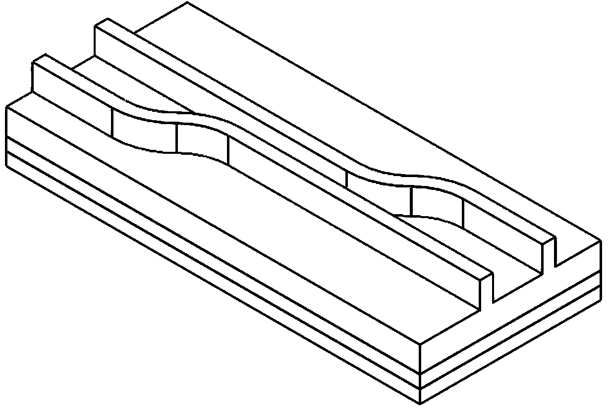
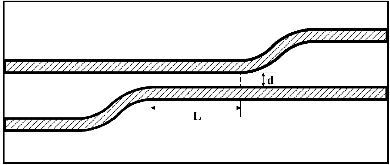
[0027] The wavelength demodulation is realized by using the wavelength demodulation device including the above-mentioned integrated optical waveguide coupler. Among them, the length of the coupling region L=400μm, the waveguide spacing d=1μm in the coupling region, and the inner ridge height H 1 =H 2 = 8 μm, outer ridge height h 1 =h 2 =6.5μm, ridge width W 1 =W 2 = 3 μm. Through BPM simulation, the relationship between P' and signal light wavelength λ is obtained as follows: Figure 5 As shown, the approximate linear detection of the 1535-1565nm band (C band) can be realized. The photodetector sensitivity is 10 -5 mW, the input signal optical power is 1 ~ 10mW, its theoretical wavelength resolution is about 1.1pm, and the wavelength resolution in practical applications is at least on the order of 10pm (0.01nm). After the external signal light to be demodulated enters the integrated optical waveguide coupler, the processor calculates P', and according to the relationship...

Embodiment 2

[0029] The wavelength demodulation is realized by using the wavelength demodulation device including the above-mentioned integrated optical waveguide coupler. Among them, the length of the coupling region L=200 μm, the waveguide spacing d=1 μm in the coupling region, and the inner ridge height H 1 =H 2 = 8 μm, outer ridge height h 1 =h 2 = 4μm, ridge width W 1 =W 2 = 3 μm. Through BPM simulation, the relationship between P' and the wavelength λ of the signal to be demodulated is obtained as follows: Figure 6 As shown, the approximate linear detection of the C-band can also be achieved, and its theoretical wavelength resolution is about 4.6pm. Although the resolution is lower, the insertion loss of the integrated optical waveguide coupler is also smaller. After the external signal light to be demodulated enters the integrated optical waveguide coupler, the processor calculates P', and according to the relationship between P' and the wavelength λ of the signal light, the ...


PUM


Abstract

The invention discloses a wave length demodulating device based on an integrated optical waveguide coupler. The wave length demodulating device comprises the integrated optical waveguide coupler, a first photoelectric detector, a second photoelectric detector, an analog-digital converting module and a processor. The two output ends of the integrated optical waveguide coupler are connected with the input end of the first photoelectric detector and the input end of the second photoelectric detector respectively, the output end of the first photoelectric detector and the output end of the second photoelectric detector are connected with the input end of the analog-digital converting module, and the output end of the analog-digital converting module is connected with the processor. According to the wave length demodulating device, wave length information of signal light to be demodulated is converted by the integrated optical waveguide coupler into power information, and dynamic and static demodulation of signals can be achieved; due to the fact that the integrated device is good in stability, the wave length demodulating device is good in disturbance resistance, simple and compact in structure and low in cost.

Description

technical field [0001] The invention belongs to the technical field of wavelength demodulation, and more specifically relates to a wavelength demodulation device based on an integrated optical waveguide coupler. Background technique [0002] In the field of modern sensing and monitoring, the technology of sensing based on the basic principle of wavelength modulation is a hot spot. The so-called wavelength modulation is to convert physical quantity information into wavelength information. This method has strong anti-interference ability (such as anti-light source fluctuation, fiber bending loss, phase ambiguity, etc.). Typical examples of wavelength modulation sensing are: fiber grating sensing, gas environment monitoring, laser light source stability monitoring, etc. Among them, the principle of fiber grating sensing is as follows: using a wide-spectrum light source incident, the fiber grating will reflect back the optical signal with a very narrow spectral width near its c...

Claims


Application Information

Patent Timeline
Patent Type & Authority Applications(China)
IPC IPC(8): G01D5/26G02B6/122
Inventor 孙军强江佳霖
Owner HUAZHONG UNIV OF SCI & TECH
Learn More