Fluorescent layer, preparation method thereof, and application of fluorescent layer in nuclear batteries

A fluorescent layer and nuclear battery technology, applied in the field of fluorescent layer, can solve problems such as material lattice damage, achieve the effects of improved adaptability, increased spectral acceptance range, and simple process

Active Publication Date: 2014-08-20
NANJING UNIV OF AERONAUTICS & ASTRONAUTICS
View PDF4 Cites 16 Cited by
  • Summary
  • Abstract
  • Description
  • Claims
  • Application Information

AI Technical Summary

Problems solved by technology

The PN junction of the energy conversion unit used in this type of nuclear battery is sensitive to radiation, and it is easy to generate defects and cause damage to the material lattice under the excitation of charged particles, which has certain constraints on the performance of the battery.

Method used


Image

  • Fluorescent layer, preparation method thereof, and application of fluorescent layer in nuclear batteries
  • Fluorescent layer, preparation method thereof, and application of fluorescent layer in nuclear batteries
  • Fluorescent layer, preparation method thereof, and application of fluorescent layer in nuclear batteries

Examples


Embodiment 1

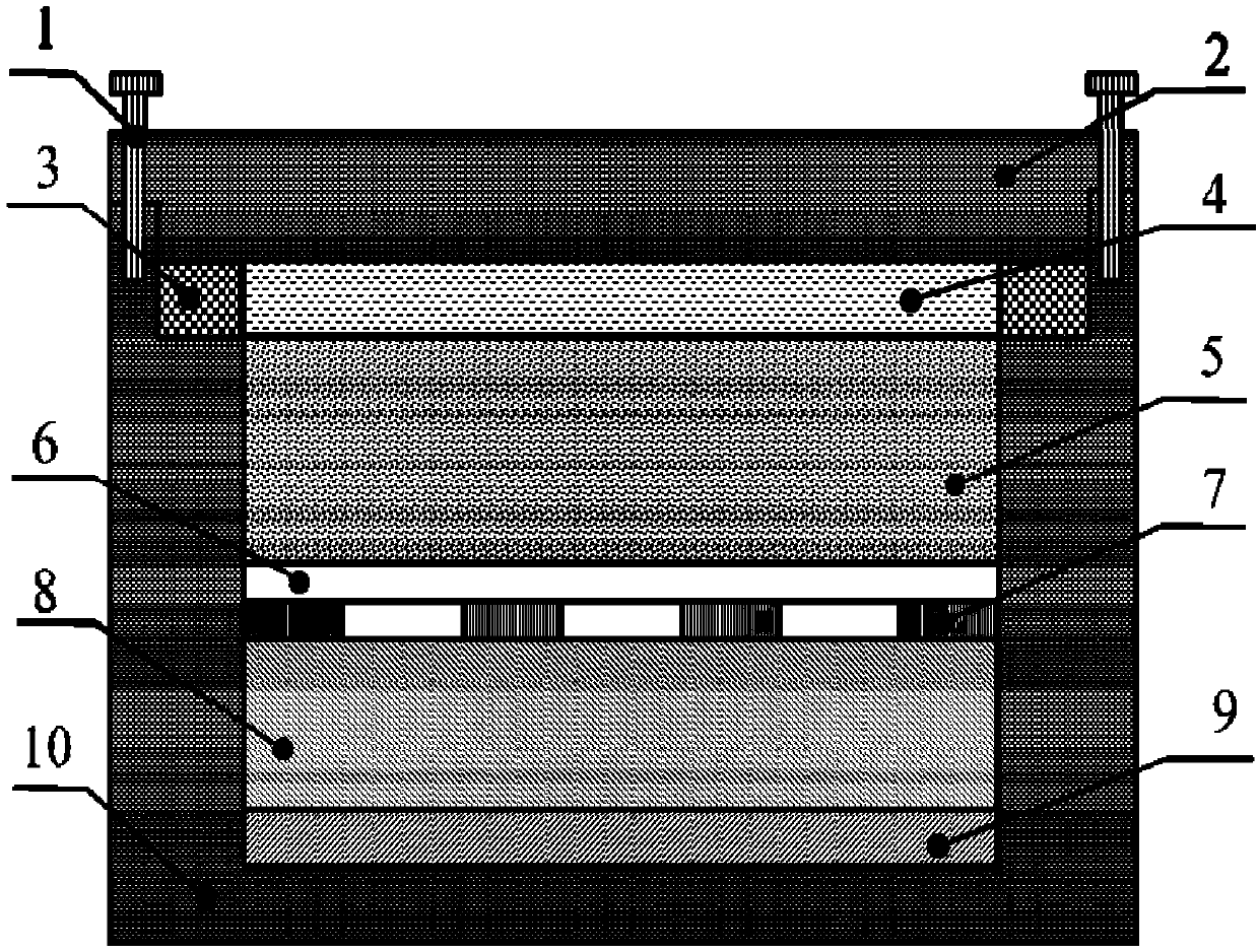
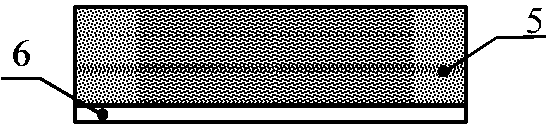
[0049] Step 1. Select a size of 30mm*30mm*0.5mm, a light transmittance of 95%, and a 1000°C resistant quartz glass sheet as the phosphor layer substrate 6, and clean it for many times with deionized water and alcohol;

[0050] Step 2: Use physical sedimentation technology to deposit a layer of ZnS:Cu fluorescent layer 5 with a thickness of 70μm on the substrate 6, and place the deposited sample at 250°C for 30 minutes and allow it to cool naturally to room temperature It can be taken out to complete the preparation of the radiation-induced fluorescent layer, and the whole preparation environment is normal pressure;

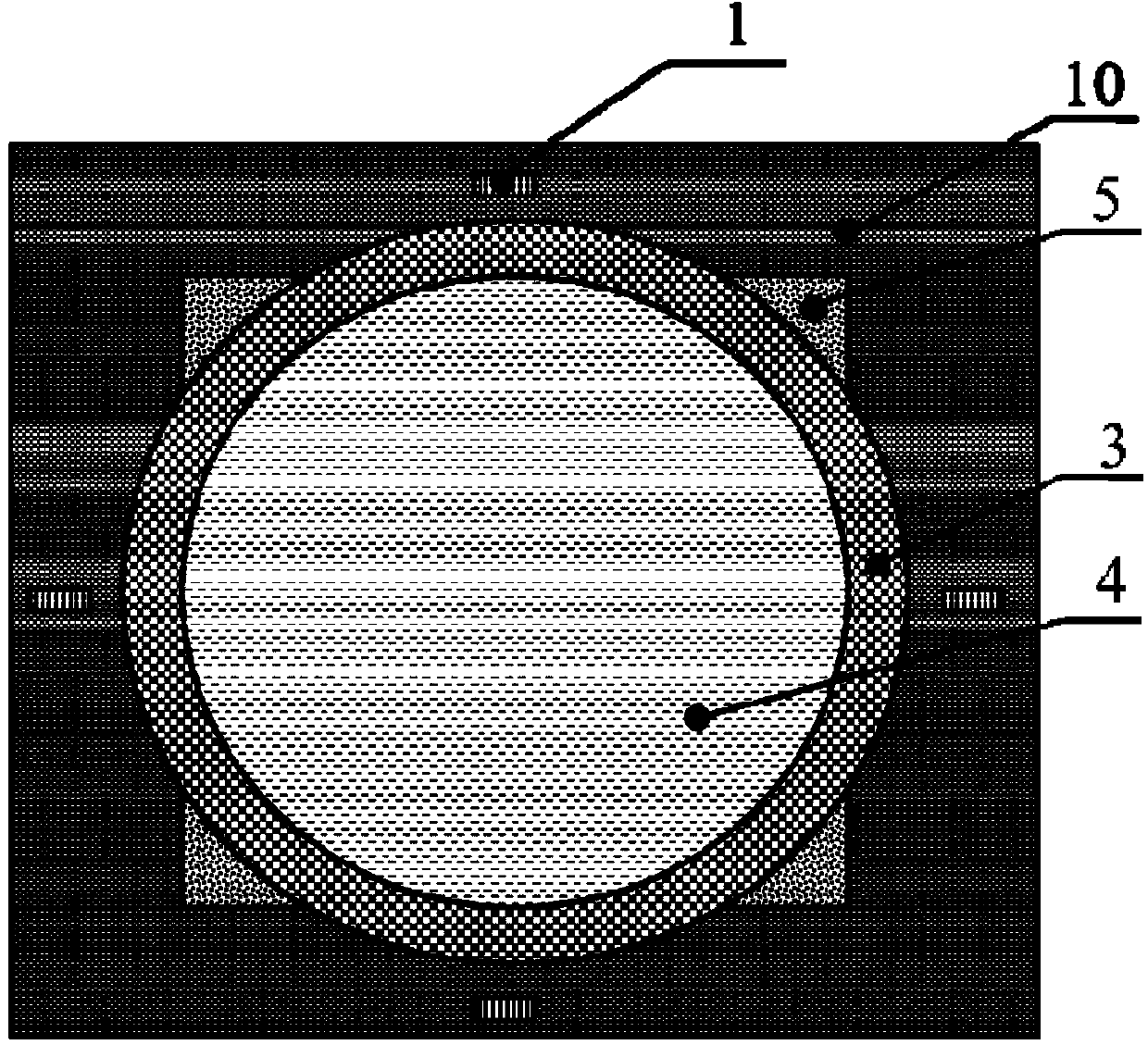
[0051] Step 3. Prepare the outer structure of the nuclear battery. The supporting device 10 is made of alumina ceramic material, rectangular parallelepiped shape, 30mm high, a rectangle with a bottom surface of 40mm*35mm, a hollow inside, and a rectangular parallelepiped shape with a depth of 20mm and a bottom surface of 35mm *30mm rectangle, cut out a circular hole wi...

Embodiment 2

[0057] This example is the same as Example 1 except for the following differences.

[0058] Step 1. Select a size of 30mm*30mm*0.3mm, a light transmittance of 95%, and a 1000℃ resistant quartz glass sheet as the phosphor layer substrate 6, and wash it with deionized water and alcohol for many times;

[0059] Step 2: Use physical sedimentation technology to deposit a layer of ZnS:Cu fluorescent layer 5 with a thickness of 90 μm on the substrate 6, place the deposited sample at 250°C for 30 minutes, and let it cool to room temperature naturally It can be taken out to complete the preparation of the fluorescent layer, and the whole preparation environment is normal pressure;

[0060] Step 5. Load a fluorescent layer composed of a ZnS:Cu fluorescent layer and a quartz glass substrate on top of the semiconductor layer, and continue to load a layer of plated radioactive metal promethium-147 and non-radioactive metal promethium on top of it, with a thickness of about 3mm ;

[0061] Step 6: ...

Embodiment 3

[0064] This example is the same as Example 1 except for the following differences.

[0065] Step 2: Use physical sedimentation technology to deposit a layer of Y with a thickness of 91 μm on the substrate 6 2 O 2 S: Eu fluorescent layer 5. Place the deposited sample at 250°C for 30 minutes and dry it, and then take it out when it is naturally cooled to room temperature. The preparation of the radiation-induced fluorescent layer is completed, and the entire preparation environment is normal pressure;

[0066] Step 5. Load Y 2 O 2 S: The radiation-induced fluorescent layer composed of Eu fluorescent layer and quartz glass substrate, on which a layer of plated radioactive metal promethium-147 and non-radioactive metal promethium is continuously loaded, the thickness is about 3mm;

[0067] Step 6. Load a sealing cover on the entire peripheral structure, encapsulate the cells of the battery, and fix the entire battery with connecting devices such as screws to complete the preparation of th...


PUM


Abstract

The invention discloses a fluorescent layer, a preparation method thereof, and an application of the fluorescent layer in nuclear batteries. A fluorescent powder layer is arranged on a glass substrate by a physical sedimentation method. The fluorescent layer is used in a nuclear battery structure and arranged between a radiation source and a photovoltaic semiconductor assembly. The fluorescent layer is used as an intermediate energy conversion medium from radiation energy to electric energy. Radiation damage of the radiation source to the photovoltaic semiconductor assembly is effectively isolated, the service life of the nuclear battery is prolonged, and the problem that a semiconductor in a radiation voltaic effect nuclear battery is easily damaged by radiation is solved. A Beta radiation source, the fluorescent layer and a photovoltaic assembly are combined into a whole by a laminated arrangement mode. The structure is compact. The effective action area can be increased. The output power of the battery can be improved. The nuclear battery has high mobility and good safety performance, and is applicable to electronic devices like monitors, signal receivers and micro controllers.

Description

Technical field [0001] The invention belongs to the fields of nuclear physics, nuclear energy applications and micro energy, and specifically relates to a fluorescent layer, a preparation method of the fluorescent layer and its application in a nuclear battery. Background technique [0002] In recent years, with the development of population and living standards, the demand for energy has also increased day by day, but with the deepening of space exploration and the advancement of high-tech energy technology industries, mankind has also put forward higher requirements for energy. In many fields such as ultra-low power devices and automatic control systems, especially in some places where replacement and maintenance are currently difficult, a long-life, efficient and stable energy supply system has great potential use value. Nuclear batteries with long life (depending on the half-life of the radioisotope), small size, light weight, strong environmental adaptability, wide operating...

Claims


Application Information

Patent Timeline
Patent Type & Authority Applications(China)
IPC IPC(8): H01L31/055G21H1/12
CPCY02E10/50Y02E10/52H01L31/055G21H1/12
Inventor 汤晓斌许志恒洪亮刘云鹏陈达
Owner NANJING UNIV OF AERONAUTICS & ASTRONAUTICS
Why Eureka
Try Eureka