Method and apparatus for operating an electronically commutated electrical machine in the event of a fault

一种运行方式、故障的技术,应用在用电装置、运输和包装、输出功率的转换装置等方向,能够解决减小电机可靠性、增大电机结构尺寸、限制功率等问题

Active Publication Date: 2014-08-20
ROBERT BOSCH GMBH
View PDF6 Cites 4 Cited by
  • Summary
  • Abstract
  • Description
  • Claims
  • Application Information

AI Technical Summary

Problems solved by technology

However, these measures have the disadvantage that the structural dimensions of the electric machine are increased due to the additional required structural elements
In addition, additional ohmic losses are generated by switches or relays, which can act as a power limiter
Due to these additionally required structural elements, the installation outlay and costs are increased and additional fault sources are created, which reduces the reliability of the motor

Method used


Image

  • Method and apparatus for operating an electronically commutated electrical machine in the event of a fault
  • Method and apparatus for operating an electronically commutated electrical machine in the event of a fault
  • Method and apparatus for operating an electronically commutated electrical machine in the event of a fault

Examples


Embodiment Construction

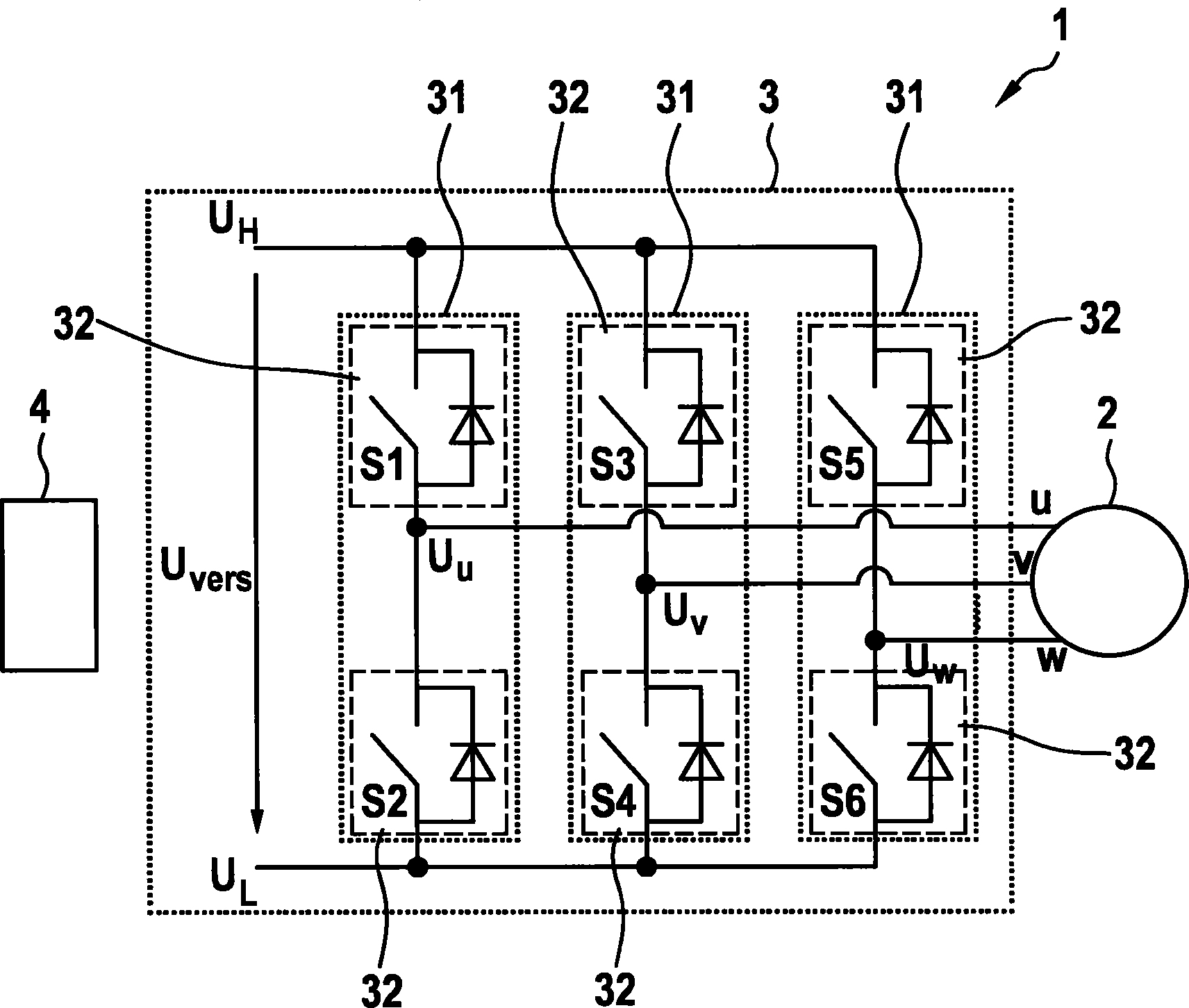
[0031] figure 1 A schematic diagram of a motor system 1 with an electronically commutated motor 2 is shown. The electric machine 2 can be designed, for example, as a synchronous machine, an asynchronous machine, a reluctance machine or the like. The electric machine 2 is designed as a multiphase, in the exemplary embodiment shown, as a three-phase and has phases U, V, W. The electric machine 2 is electronically commutated, that is to say varying phase voltages or phase currents are applied to the electric machine 2 or to phase branches of the electric machine 2 according to a commutation pattern.

[0032] Phase voltage U U , U V , U W It is produced by means of a driver circuit 3 which is controlled by a control unit 4 . The control unit 4 can be designed, for example, as a microcontroller or the like and supplies control signals with which the semiconductor switches S1 to S6 of the driver circuit 3 can be controlled. The semiconductor switches S1 to S6 are preferably co...


PUM


Abstract

The invention relates to a method for operating a multiphase electrical machine (2) in the event of a fault, wherein the electrical machine (2) is driven with the aid of a driver circuit (3), wherein the driver circuit (3) has half-bridge circuits (31), each associated with a phase (U, V, W), and bridge paths (32) for connecting or disconnecting predetermined voltage potentials to / from the respective phases (U, V, W) of the electrical machine (2), wherein one or more of the bridge paths (32) are operated according to a first fault operating mode if a fault is detected, wherein, in the first fault operating mode, the one or more bridge paths (32) are controlled in such a manner that said paths connect a first of the predetermined voltage potentials to the phase (U, V, W) via a predetermined electrical resistor.

Description

technical field [0001] The invention relates to an electronically commutated electric machine, in particular a multiphase electric machine, which is controlled by means of a drive circuit. The invention also relates to a method for controlling an electric machine in the event of a fault. Background technique [0002] Electronically commutated electric machines, such as those used in electric drives, are controlled by means of a drive circuit (inverter). For this purpose, the drive circuit has semiconductor switches which are switched in a commutation pattern offset from one another in order to supply current to several phase branches of the electric machine. For example, such a driver circuit for a three-phase electric machine can be implemented as a so-called B6 circuit, which has three half-bridges, which each include two semiconductor switches connected in series. The half bridges are used to generate a phase voltage respectively. A supply voltage is applied to the hal...

Claims


Application Information

Patent Timeline
Patent Type & Authority Applications(China)
IPC IPC(8): H02P27/06H02P25/22H02P29/02H02M1/32
CPCH02P29/022H02P27/06H02M1/32H02P25/22H02P29/032B60L3/0061B60L2240/526Y02T10/64
Inventor B·迪特默E·霍夫曼
Owner ROBERT BOSCH GMBH
Why Eureka
Try Eureka