A method of making a hydrogen separation composite membrane

A technology for manufacturing gas and separation systems, applied in separation methods, hydrogen separation, diffusion hydrogen separation, etc., can solve problems that cannot meet industrial needs, damage functional manufacturing efficiency, etc.

Inactive Publication Date: 2014-08-27
SHELL INT RES MAATSCHAPPIJ BV
View PDF9 Cites 0 Cited by
  • Summary
  • Abstract
  • Description
  • Claims
  • Application Information

AI Technical Summary

Problems solved by technology

[0008] However, manufacturing efficiency cannot be increased at the expense of functionality
In many applications, the purity of the gas product is critical, and cutting corners in the manufacture of gas separation systems often result in systems that do not meet industry needs

Method used


Image

  • A method of making a hydrogen separation composite membrane
  • A method of making a hydrogen separation composite membrane
  • A method of making a hydrogen separation composite membrane

Examples


Embodiment 1

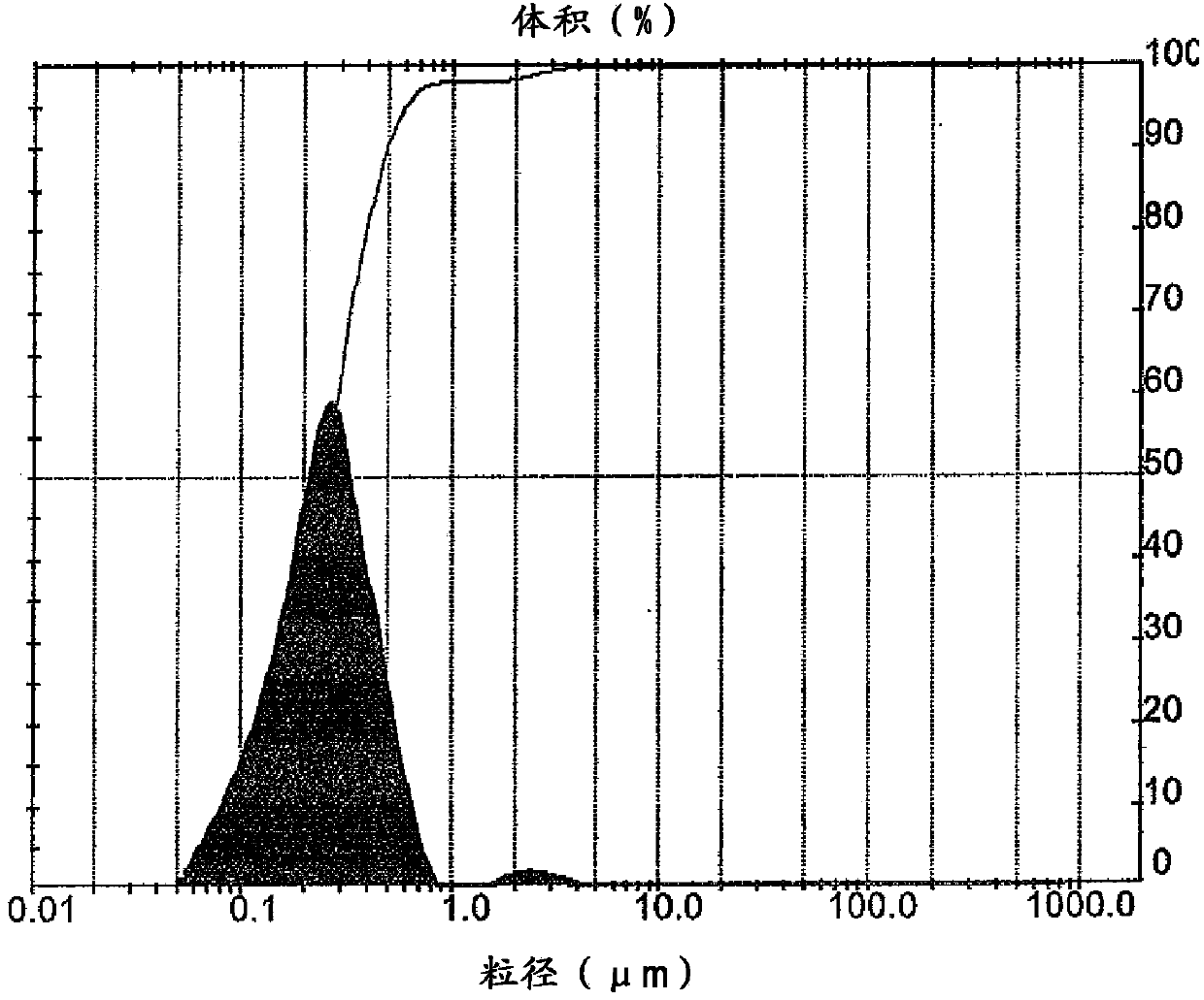
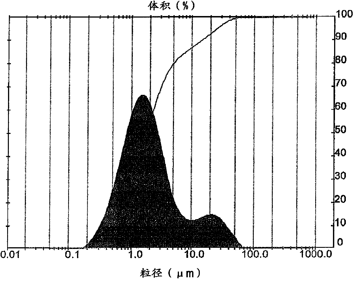
[0127] This example illustrates the reduction in surface roughness obtained by the method of the invention. In this example, an inside-out pressed cylindrical porous support made of 310 stainless steel was obtained from a commercial supplier. The initial surface roughness of the carrier was measured by using ST400 optical profilometer marketed and sold by Nanovea.RTM. Then make the vector with figure 2 The granular materials shown in were contacted using the slurry contact method described above. After removing excess particulate material, use figure 1 The granular material is subjected to a second contacting step. The surface roughness results are shown in Table 1.

[0128] Table 1

[0129]

[0130] After the particulate material contacting step, a thin film of palladium is deposited on the support treated with the sequential electroless plating and polishing steps as described above. The resulting gas separation system was then tested at 15 psi, showing 26m 3 / (...

Embodiment 2

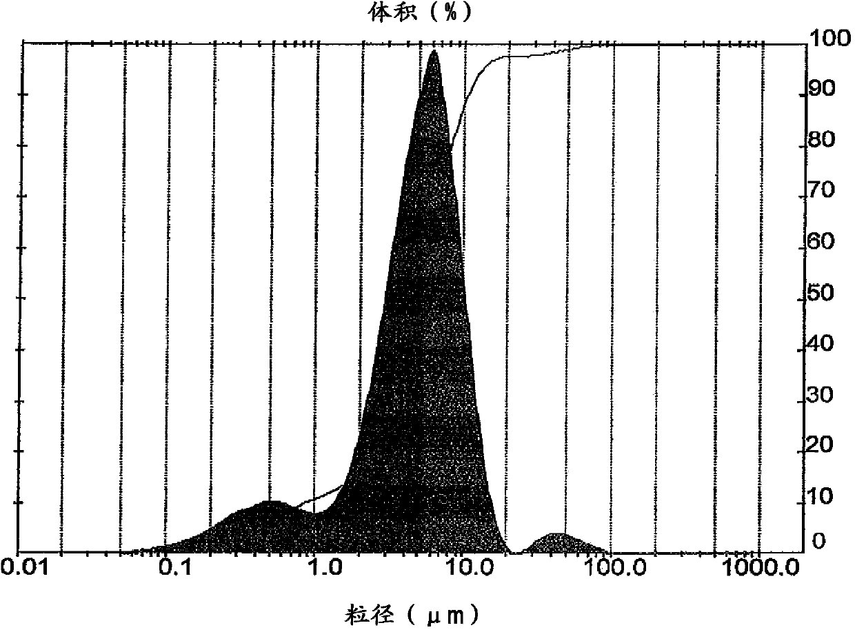
[0132] This example illustrates the reduction in surface roughness obtained by the method of the invention utilizing three contacting steps. In this example, an inside-out pressed cylindrical porous support made of 310 stainless steel was obtained from a commercial supplier. The initial surface roughness of the carrier was measured by using ST400 optical profilometer marketed and sold by Nanovea.RTM. Then make the vector with Figure 4 The granular materials shown in were contacted using the slurry contact method described above. use image 3 and 2 The exposure and associated steps were repeated two more times for the materials shown in . Surface roughness results are shown in Table 2.

[0133] Table 2

[0134]

[0135] After the particulate material contacting step, a thin film of palladium is deposited on the support treated with the sequential electroless plating and polishing steps as described above. The film has a 35.5m 3 / (m 2 hr bar) and did not show any ...

Embodiment 3

[0137] This example illustrates the reduction in surface roughness obtained by the method of the invention using four contacting steps as described above. In this example, an inside-out pressed cylindrical porous support made of 310 stainless steel was obtained from a commercial supplier. The initial surface roughness of the carrier was measured by using ST400 optical profilometer marketed and sold by Nanovea.RTM. Then make the vector with Figure 4 The granular materials shown in were contacted using the slurry contact method described above. use image 3 , 2 The exposure and associated steps were repeated three more times with the materials shown in 1. Surface roughness results are shown in Table 3.

[0138] table 3

[0139]

[0140] After the particulate material contacting step, a thin film of palladium is deposited on the support treated with the sequential electroless plating and polishing steps as described above. The membrane showed no leaks when pressurize...


PUM

PropertyMeasurementUnit
surface roughnessaaaaaaaaaa
particle sizeaaaaaaaaaa
sizeaaaaaaaaaa

Abstract

A method of making a gas separation system is described. The method comprises the steps of (1) providing a porous support having an initial mean pore size and initial surface roughness and (2) applying a particulate material to a surface of the porous support to (a) functionally reduce the mean pore size of the support and (b) functionally reduce the measurable surface roughness of the support. Additional layers of particulate material of decreasing size are applied to further reduce the mean pore size and reduce the roughness of the support. When the support reaches the desired level of smoothness a thin membrane of gas selective material is deposited thereon. The membrane and support are then annealed under conditions that prevent or substantially reduce cracking of the membrane during commercial use.

Description

technical field [0001] The present invention relates to a method of making a gas separation system. In particular, the present invention relates to a method of making a gas separation system that is particularly well suited for separating hydrogen from mixed gas streams. Background technique [0002] A variety of industrial applications require an inexpensive source of purified gases. Hydrogen is an example of the gas. Inexpensive sources of purified hydrogen are sought in various industrial chemical processes as well as in the production of energy in fuel cell power systems. Similarly, an inexpensive method of purifying hydrogen could significantly expand the applicability of hydrocarbon reforming, reforming reactors, and water-gas shift reactions. To meet the demand for inexpensive purified hydrogen, much research has been conducted to develop more efficient hydrogen permeable gas separation membrane systems that can be used to selectively recover hydrogen from differen...

Claims


Application Information

Patent Timeline
Patent Type & Authority Applications(China)
IPC IPC(8): B01D53/22B01D69/10B01D69/12B01D69/02B01D67/00C01B3/50
CPCB01D67/0095B01D69/12B01D2323/08B01D71/022B01D67/0076B01D67/0046B01D67/0039B01D53/228B01D2325/22C01B3/503B01D69/10B01D67/0069
Inventor J·C·索凯蒂斯
Owner SHELL INT RES MAATSCHAPPIJ BV
Why Eureka
Try Eureka