Ground driving motor of teetch-difference deceleration screw pump

A technology for driving motors and screw pumps, applied in gear transmissions, electrical components, electromechanical devices, etc., can solve the problems of small cost reduction, increased maintenance costs, environmental pollution, etc., to reduce the probability of seal failure, improve The effect of work safety and production cost reduction

Inactive Publication Date: 2014-09-10
ZHEJIANG DEQING XICHUAN ELECTRICAL SCI & TECH
View PDF12 Cites 5 Cited by
  • Summary
  • Abstract
  • Description
  • Claims
  • Application Information

AI Technical Summary

Problems solved by technology

[0003] After retrieval of Chinese patents, including invention patent (invention name: screw pump drive reducer for oil exploitation, application number: 200610016273.0) and utility model patent (utility model name: new screw pump ground drive reduction box device, application number: 98244884.8 ) both disclose the combination of the motor and the deceleration mechanism, but both have their limitations: because the motors used in the two patents are placed on the side of the sucker rod, they can be called partial drives. The center of gravity of the tree is not on the axis of the sucker rod, which causes serious shaking during work, which makes the sucker rod wear badly, which makes the sealing structure more likely to fail and cause environmental pollution, and even breaks due to partial wear all the year round, which is not safe and increases Post-maintenance cost
[0004] In addition, invention patent (invention name: direct drive permanent magnet synchronous motor for screw pump, application number: 200610155454.1) and utility model patent (utility model name: hollow vertical shaft permanent magnet synchronous drive device for screw pump, application number: 200820228282.0) Both have also disclosed the scheme of combining the gear reduction device and the permanent magnet synchronous motor, but there are safety hazards such as liquid easily entering the inner cavity of the motor after the seal fails, causing a short circuit.
Furthermore, although the motor disclosed in the invention patent (invention name: collimated drive permanent magnet synchronous motor, application number: 201110335373.0) solves the above problems well, but because its reduction ratio is ≤4, the reduction in cost and volume is not large

Method used


Image

  • Ground driving motor of teetch-difference deceleration screw pump
  • Ground driving motor of teetch-difference deceleration screw pump

Examples


Embodiment Construction

[0014] The specific implementation manner of the present invention will be described in detail below in conjunction with the accompanying drawings.

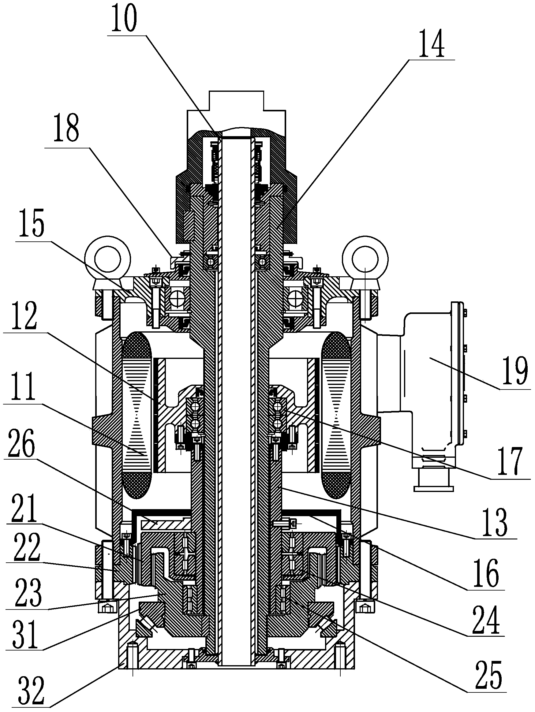
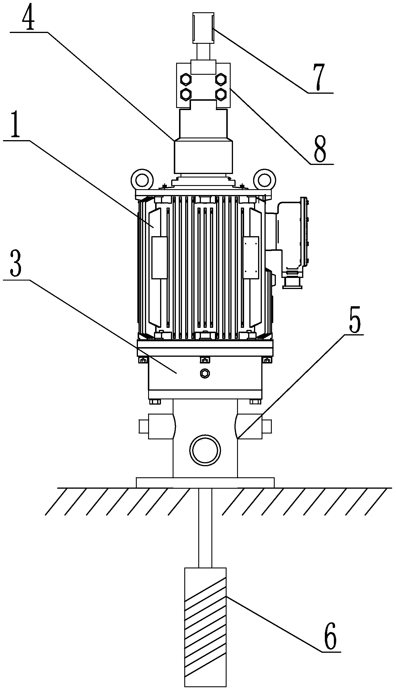
[0015] Such as figure 1 , figure 2 The shown ground driving motor of a differential gear reduction screw pump includes a motor drive part 1 arranged at the upper end and a bearing support assembly 3 arranged at the lower end. The drive part 1 includes a stator 11, a rotor 12, a main shaft 14, an eccentric Shaft 13 and rotor bearing 17, the driving part 1 is installed inside the casing, a junction box 19 is arranged outside the casing, and an upper end cover 15 is fixed on the upper end of the casing by bolts, the main shaft 12 runs through the upper end cover 15, and the main shaft 12 The part where the upper end cover 15 is exposed is equipped with an outer shaft 4, and a rotating sealing cover 18 is also provided between the outer shaft 4 and the upper end cover 15. The outer ring of the rotor bearing 17 is matched with the r...


PUM


Abstract

The invention relates to a ground driving motor of a teeth-difference deceleration screw pump. The ground driving motor comprises a motor driving portion and a bearing support component, wherein the motor driving portion comprises a stator, a rotor, a spindle, an eccentric shaft and a rotor bearing, the bearing support component comprises a load bearing bearing and a support seat, the motor driving portion and the bearing support component are connected via a gear reduction mechanism, teeth-difference gear groups are adopted by a gear reducer which comprises a fixed gear ring, a planet gear ring and an output gear ring, the fixed gear ring is fixed between a shell and the support seat via bolts, an outer-wall gear of the planet gear ring is meshed with an inner-wall gear of the fixed gear ring, a first gear ring bearing is arranged between the planet gear ring and the eccentric shaft, an outer-wall gear of the output gear ring is meshed with an inner-wall gear of the planet gear ring, a second gear ring bearing is arranged between the output gear ring and the eccentric shaft, and the output gear ring is fixedly connected with the spindle. The ground driving motor of the teeth-difference deceleration screw pump is capable of avoiding eccentric wearing of an oil pumping polish rod caused by eccentricity, decreasing a sealing invalidation happening rate and improving operation safety.

Description

technical field [0001] The invention relates to a motor structure, in particular to a ground drive motor for a differential tooth deceleration screw pump. Background technique [0002] At present, most of the screw pump direct drive motors used in oil fields use permanent magnet synchronous direct drive motors. Their biggest feature is the use of permanent magnets as the main magnetic field. However, the raw materials of permanent magnets are non-renewable rare earth resources. In recent years, the price of rare earths has soared. It occupies more than one-third of the cost of a permanent magnet synchronous motor, or even a higher proportion, which greatly reduces the cost performance of permanent magnet synchronous motors, and the cost is far higher than that of asynchronous machines. In addition, the direct drive motor with low speed and high torque is larger than ordinary asynchronous motor with gearbox, which increases the load of oil production wells on the one hand, an...

Claims


Application Information

Patent Timeline
Patent Type & Authority Applications(China)
IPC IPC(8): H02K7/116F16H1/32
Inventor 李骏候国安张焱平
Owner ZHEJIANG DEQING XICHUAN ELECTRICAL SCI & TECH
Why Eureka
Try Eureka