Photoelectric circulating generator unit

A technology for circulating generator sets and generator sets, applied in electrical components, electromechanical devices, etc., can solve the problems of high cost of photovoltaic systems, difficulty in accurately predicting the power generation of the system, and no competitive advantage.

Inactive Publication Date: 2014-09-10
匡仲平
View PDF0 Cites 1 Cited by
  • Summary
  • Abstract
  • Description
  • Claims
  • Application Information

AI Technical Summary

Problems solved by technology

[0003] (1) The light energy distribution density of solar radiation is small, about 100W/m2, which requires a huge area
[0004] (2) It is greatly affected by weather conditions such as seasons, day and night, and cloudy or sunny, so it cannot generate power continuously. The annual power generation hours are re

Method used


Image

  • Photoelectric circulating generator unit
  • Photoelectric circulating generator unit
  • Photoelectric circulating generator unit

Examples


Embodiment Construction

[0029] specific implementation plan

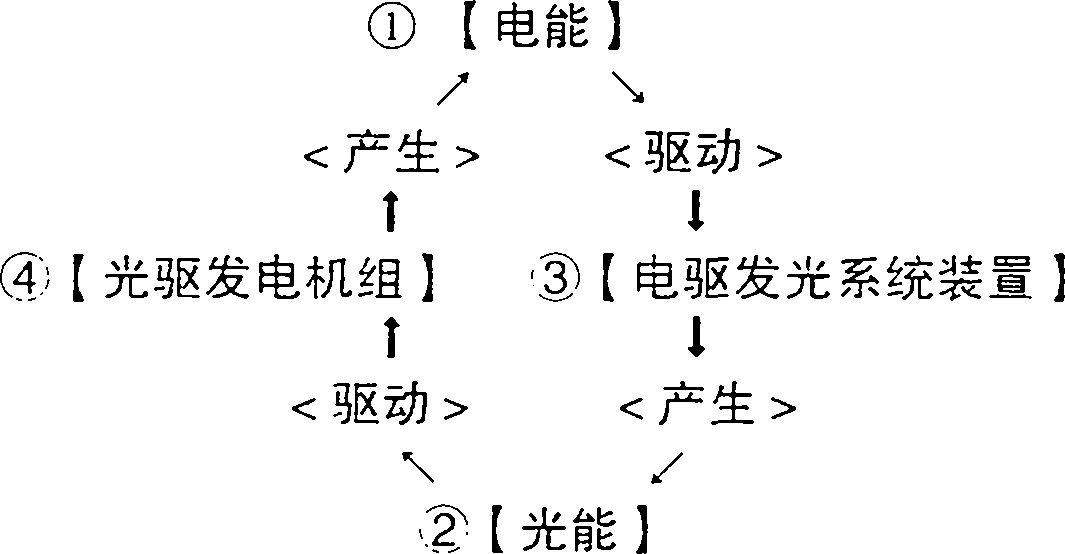
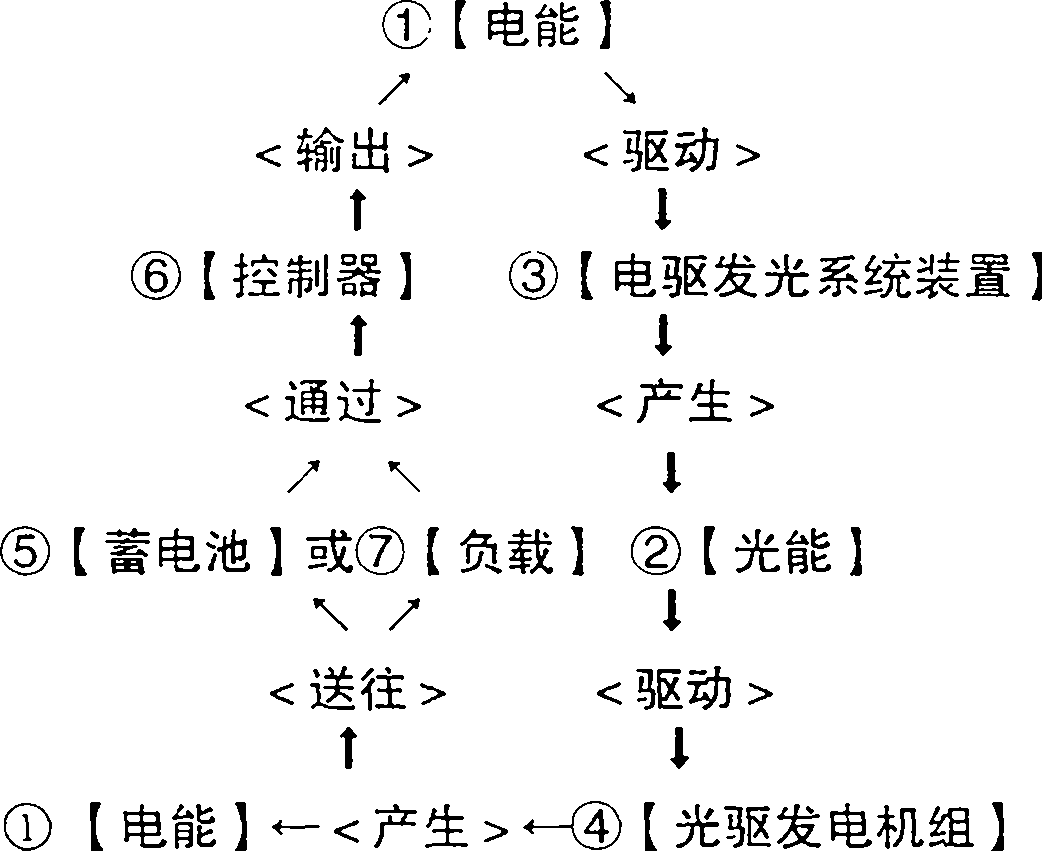
[0030] (1), the system device is composed of ③[electric drive lighting system device] and ④[optical drive generator set] with high light efficiency, high stability, high density strong light irradiation, such as photovoltaic power generation, photochemical power generation, light induction power generation, photobiological Power generation, photothermal generator set and its electric drive photovoltaic cell assembly (array), ⑤ [battery], ⑥ [controller], inverter, the user is the electric drive light ⑦ [load] and other accessories. Among them, electric drive ②[light energy] battery components and ⑤[battery] are the power system, ⑥[controller] and inverter are the control and protection system, ⑦[load] is the system terminal, etc.

[0031] (2), ①[electrical energy] is converted into ②[light energy] through ③[electrically driven light-emitting system device], and ②[light energy] is converted into ①[electrical energy] through ④[photoelectric g...


PUM


Abstract

The invention discloses a photoelectric circulating generator unit, and belongs to the technical field of improvement and innovation, which are saving in sources, low-carbon, energy-saving, environment-friendly and conductive to green development, on equipment of optical drive power generation technology relating to new energy. The technical problems to be solved include: technical butt joint and integration of an electric drive lighting system device (3) and an optical drive generator unit (4), and circular interchange of electric energy (1) and optical energy (2). The technical key point to solve the above problems is to replace/abandon natural solar light energy power generation by electric drive optical energy power generation. The main applications are to greatly improve radiation illumination intensity, density and stability and photoelectric conversion efficiency for converting radiation to electric current at an energy consumption ratio that electric energy production is far higher than electricity consumption (conservatively estimate to be more than 16:1), greatly reduce cost per watt, effectively avoid influence of seasons, day and night, cloud and sun and other meterological conditions, enable to optical energy generator unit to continuously generate electricity, ensure annual generating hours, and accurately predict electric energy production of the system.

Description

technical field [0001] This device involves the improvement and innovation of new energy-related high-end equipment manufacturing, low-carbon technology, resource conservation, energy conservation and environmental protection, and photovoltaic power generation technology equipment and facilities that are conducive to green development. Background technique [0002] At present, the power generation of photovoltaic power plants at home and abroad is completely dependent on the energy (mainly solar energy) from the sun, the outer celestial body of the earth, which is the huge energy released by the fusion of hydrogen nuclei in the sun at ultra-high temperatures. Its flaws are: [0003] (1) The light energy distribution density of solar radiation is small, about 100W / m2, which requires a huge area. [0004] (2) It is greatly affected by weather conditions such as seasons, day and night, and cloudy or sunny, so it cannot generate power continuously. The annual power generation h...

Claims


Application Information

Patent Timeline
IPC IPC(8): H02K53/00
Inventor 匡仲平
Owner 匡仲平
Why Eureka
Try Eureka