Liquid oxygen and liquid nitrogen preparation device and method

A liquid oxygen and liquid nitrogen technology, applied in the field of liquid oxygen and liquid nitrogen production devices, can solve problems such as increasing the difficulty of operation, and achieve the effects of high production efficiency, high product extraction rate and simple operation

Inactive Publication Date: 2014-09-24
KAIFENG AIR SEPARATION GROUP
View PDF8 Cites 37 Cited by
  • Summary
  • Abstract
  • Description
  • Claims
  • Application Information

AI Technical Summary

Problems solved by technology

The above process forms all need to use an additional air booster or nitrogen booster to pressurize the raw material gas, which increases the difficulty of operation.

Method used


Image

  • Liquid oxygen and liquid nitrogen preparation device and method

Examples


Embodiment 1

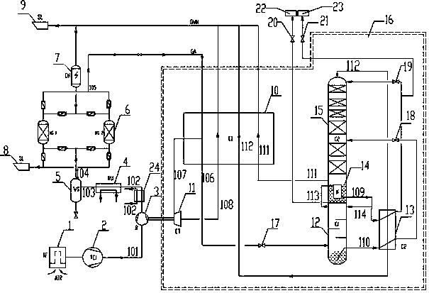
[0024] A device for producing liquid oxygen and liquid nitrogen, such as figure 1As shown, it includes an air compression system, a pre-cooling system, a purification system and a cold box 16, and the air compression system includes a self-cleaning air filter 1 and an air compressor 2 connected to the self-cleaning air filter. Cold system comprises cooler 24 and air-conditioning unit 4, and described purification system comprises molecular sieve adsorber 6, electric heater 7, first muffler 8 and second muffler 9, and electric heater heats the dirty nitrogen that cold box comes over to 175 After ℃, it is sent to the molecular sieve adsorber for molecular sieve regeneration, and the silencer plays the role of eliminating noise for the venting of dirty nitrogen and nitrogen. The cold box includes a main heat exchanger 10, an expansion end 11 of a turboexpander and a fractionation tower; The air compressor is connected with the supercharged end 3 of a turboexpander through the fir...

Embodiment 2

[0028] A liquid oxygen and liquid nitrogen production method, using a liquid oxygen and liquid nitrogen production device, the device is the first embodiment of the liquid oxygen and liquid nitrogen production device, which will not be repeated here. The method includes:

[0029] 1) The raw material of this device is air. The air first passes through the self-cleaning air filter 1 to filter out impurities and then enters the air compressor 2. The compressed gas pressure is 0.6~1.0MPa and the temperature is 40°C. The compressed gas is directly Enter the booster end 3 of the turbo expander to pressurize. After the pressurization, it is cooled to 40°C by the cooler 24 and then enters the air-conditioning unit 4 to be cooled again to 5~8°C. The cooled gas is separated by the separator 5 to remove free After the water enters the molecular sieve adsorber for adsorption, the gas enters the cold box 16 after absorbing water, carbon dioxide and some hydrocarbons through the adsorber, a...


PUM


Abstract

The invention relates to a liquid oxygen and liquid nitrogen preparation device and method. The device comprises a self-cleaning air filter, an air compressor, a cold air unit, a separator, a molecular sieve adsorber, a main heat exchanger, a lower tower, an upper tower, a subcooler and an expander. The raw material of the device is air. The air passes through the self-cleaning air filter, the air compressor, the supercharging end of the expander, the cold air unit and the molecular sieve adsorber in sequence and then enters a cold box; after passing through the main heat exchanger, a part of the air is pumped out of the lower middle portion of the main heat exchanger and enters the expanding end of the turbo expander for adiabatic expansion; expanded air is reheated by the main heat exchanger and then sent out of the cold box; the remaining air is cooled to a liquefaction point, goes out of the main heat exchanger and enters the lower tower for rectification. A liquid oxygen product is pumped out of the bottom of the lower tower and then conveyed to a liquid oxygen storage tank; a liquid nitrogen product is pumped out of the main cold liquid nitrogen side and then conveyed to a liquid nitrogen storage tank. According to the liquid oxygen and liquid nitrogen preparation device and method, operation is simple in the technological process, the extraction rate is high, energy consumption is low, and meanwhile equipment investment cost is low.

Description

technical field [0001] The invention relates to the field of air separation, in particular to a device and method for preparing liquid oxygen and liquid nitrogen. Background technique [0002] With the rapid development of all walks of life, the demand for industrial gases has also increased significantly, especially the demand for liquid products has increased year by year, at a rate of 15% to 20% per year. Because liquid air separation products have the advantages of convenient storage, convenient supply, guaranteed quality, and high transmission efficiency, they are more and more used by users, and the market potential is great. If the by-products of the air separation plant alone cannot meet the market demand, the application of the all-liquid air separation plant has become a trend. With the great improvement of traffic conditions and the pursuit of higher economic benefits, liquid air products are more and more popular with users due to their good quality, low transpo...

Claims


Application Information

Patent Timeline
Patent Type & Authority Applications(China)
IPC IPC(8): F25J3/04
Inventor 王庆波卓跃光郑三七张建松党辉郭士雪彭喜魁孟松涛郑书亮
Owner KAIFENG AIR SEPARATION GROUP
Why Eureka
Try Eureka