
A Two-Photon Fluorescence Stimulated Emission Differential Super-resolution Microscopy Method and Device
A two-photon fluorescence and stimulated emission technology, which is applied in the field of super-resolution, can solve the problems of strong scattering and limited imaging depth of the microscope, and achieve the effect of weakening scattering, high resolution and simple device
- Summary
- Abstract
- Description
- Claims
- Application Information
AI Technical Summary
Problems solved by technology
Method used
Image

Examples
Embodiment Construction
[0042] The present invention will be described in detail below in conjunction with the embodiments and accompanying drawings, but the present invention is not limited thereto.
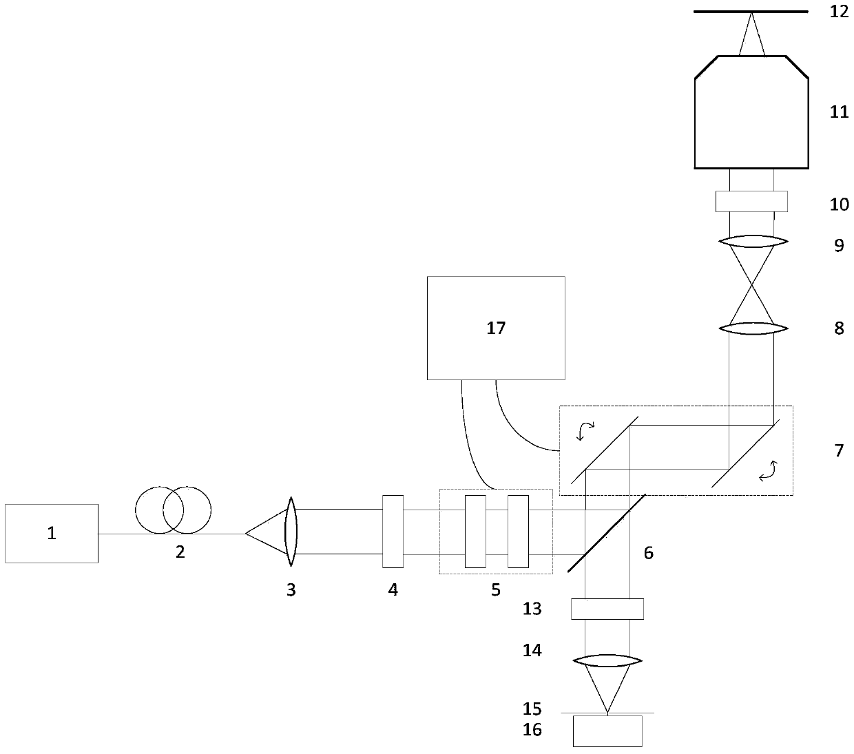
[0043] Such as figure 1 As shown, the fluorescence stimulated emission differential super-resolution microscopy device includes: femtosecond pulsed laser 1, single-mode fiber 2, collimator lens 3, polarizer 4, liquid crystal polarization converter 5, dichroic mirror 6, scanning Galvanometer system 7, scanning lens 8, field lens 9, 1 / 4 wave plate 10, microscope objective lens 11, sample stage 12, optical filter 13, focusing lens 14, pinhole 15, detector 16, controller 17.
[0044] Single-mode optical fiber 2, collimator lens 3, polarizer 4, liquid crystal polarization converter 5, dichroic mirror 6 are located on the optical axis of the outgoing beam of femtosecond pulse laser 1 in sequence, and the light transmission axis of polarizer 4 Parallel to the vertical direction, the scanning galvanometer sys...
PUM
 Abstract
Description
Claims
Application Information