Wire-cut electric discharge machine wire transport mechanism capable of realizing accurate closed-loop control on tension of electrode wire

A technology of closed-loop control and electric discharge wire, which is applied in the direction of electrode manufacturing, manufacturing tools, electric processing equipment, etc., can solve the problem of inaccurate real-time dynamic control of tension, and achieve the effect of precise control

Active Publication Date: 2014-10-01
江苏冬庆数控机床有限公司
View PDF10 Cites 16 Cited by
  • Summary
  • Abstract
  • Description
  • Claims
  • Application Information

AI Technical Summary

Problems solved by technology

[0006] The purpose of the present invention is to provide a wire-feeding mechanism of a wire electric discharge machine for precise closed-loop control of the tension of the electrode wire, so as to solve the problem of inaccurate real-time dynamic control of the tension existing in the prior art

Method used


Image

  • Wire-cut electric discharge machine wire transport mechanism capable of realizing accurate closed-loop control on tension of electrode wire
  • Wire-cut electric discharge machine wire transport mechanism capable of realizing accurate closed-loop control on tension of electrode wire
  • Wire-cut electric discharge machine wire transport mechanism capable of realizing accurate closed-loop control on tension of electrode wire

Examples


Embodiment 1

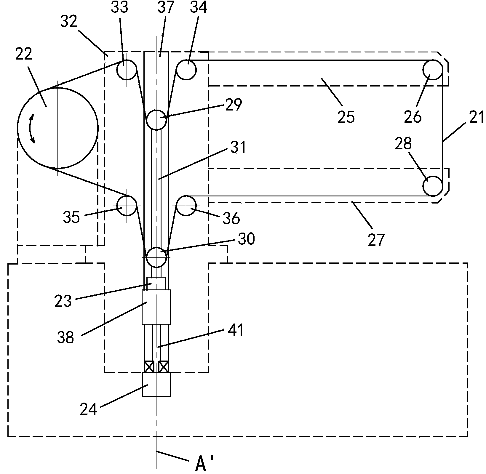
[0036] Embodiment one: see figure 2 , Figure 5 -6 shows:

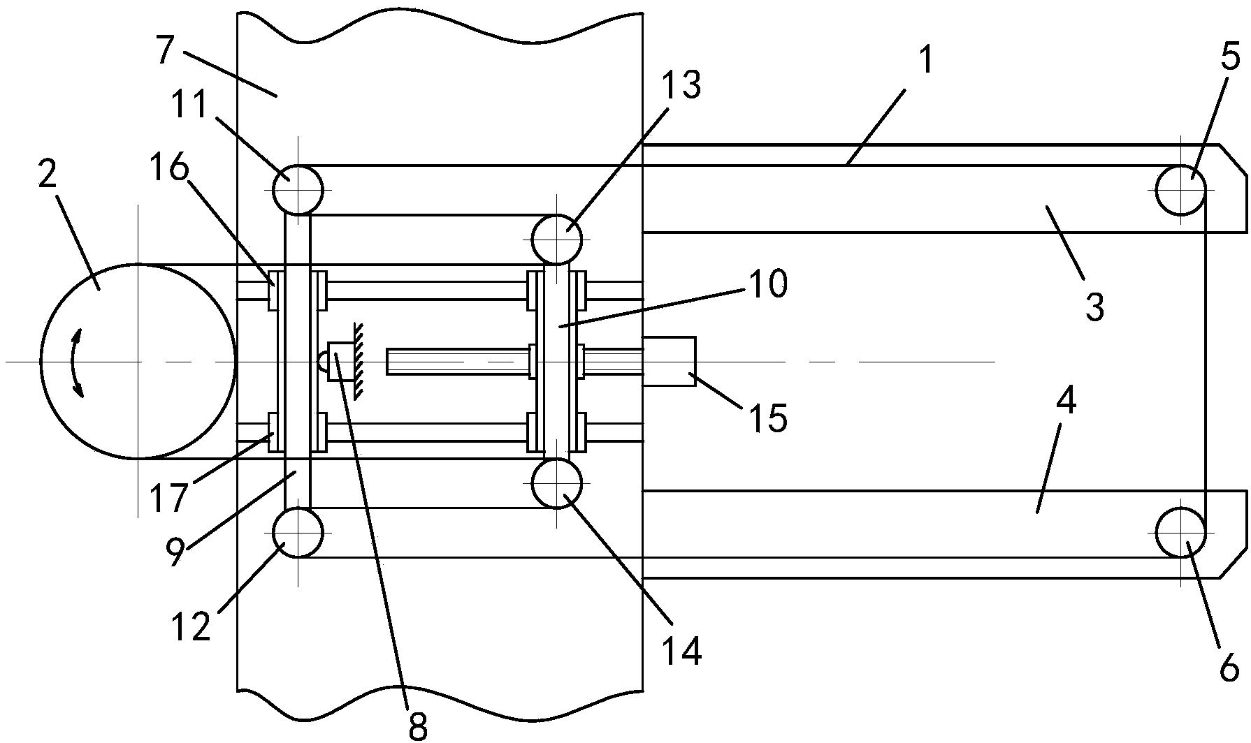
[0037] A wire feeding mechanism of a wire electric discharge machine for precise closed-loop control of electrode wire tension, see figure 2 As shown, it includes an annular closed electrode wire 21, a wire storage tube 22, several reversing wheels, a load cell 23, a driving device 24, an upper tension wheel 29 and a lower tension wheel 30, which are located at the end of the upper wire frame 25 of the wire cutting machine. The upper guide wheel 26 and the lower guide wheel 28 located at the end of the lower wire frame 27 of the wire cutting machine.

[0038] see figure 2 As shown, the upper tension wheel 29 and the lower tension wheel 30 are arranged vertically apart from each other, and the two are connected by a connecting plate 31 . The upper tensioning wheel 29, the lower tensioning wheel 30 and the connecting plate 31 form a tensioning part; the tensioning part is slidably connected to the column 32 of th...

Embodiment 2

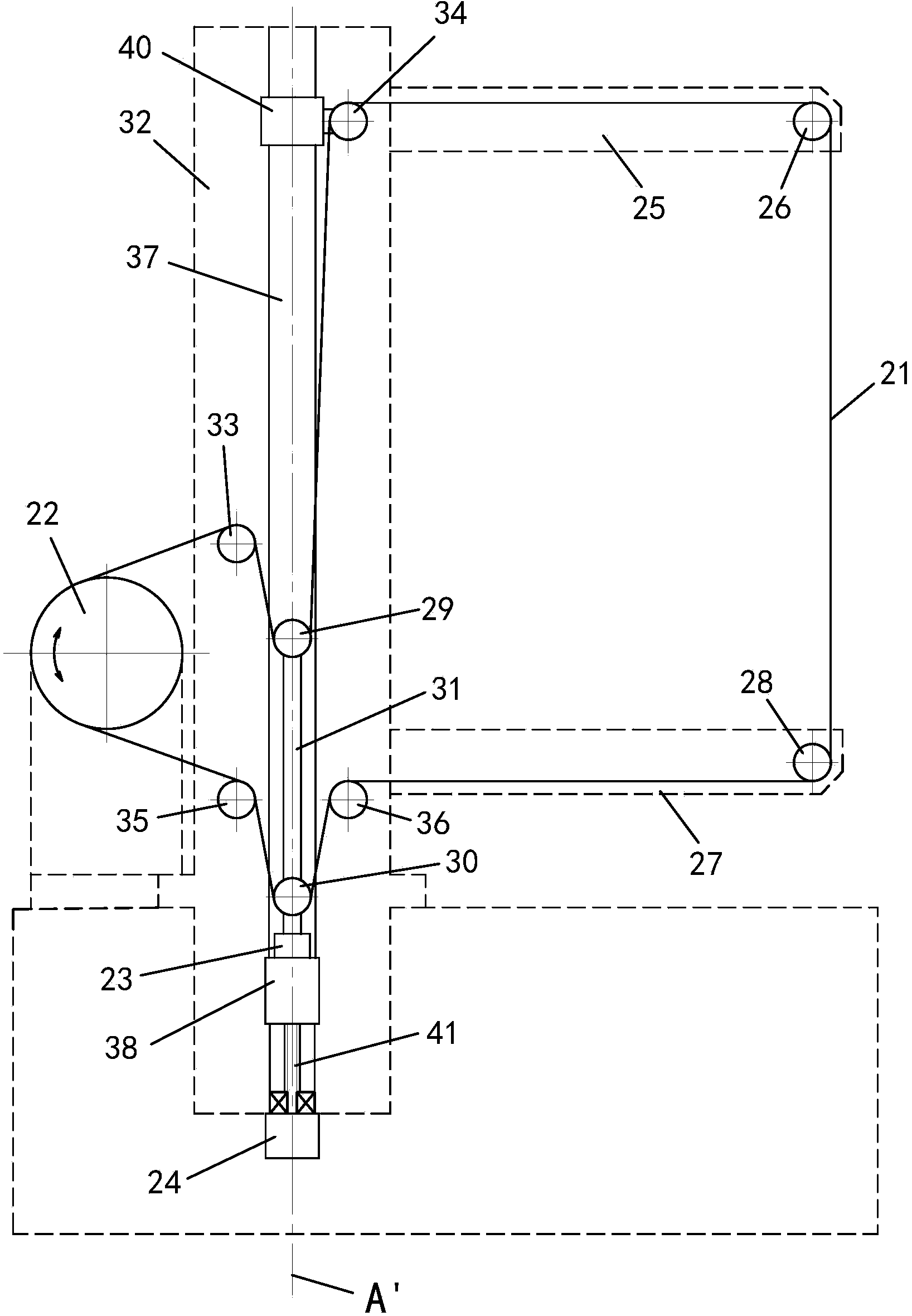
[0045] Embodiment two: see image 3 Shown:

[0046] A wire feeding mechanism of a wire electric discharge machine for precise closed-loop control of electrode wire tension. The difference from Embodiment 1 is that there is a third slider 40 on the linear slide rail 37, and the upper right reversing wheel 34 It is fixed on the third slider 40 so that the upper right reversing wheel 34 can move up and down to follow the upper guide wheel 26 for position adjustment. In this way, while the upper guide wheel 26 is adjusted to meet the requirements for cutting and processing workpieces of different heights, the upper right reversing wheel 34 is moved synchronously to realize the situation that the upper and lower halves of the ring-shaped closed electrode wire 21 are all in a horizontal state. unchanged, so that the state that the upper tension wheel 29 detects the wire tension of twice the upper half remains unchanged. Upper left reversing wheel 33 and two lower reversing wheels ...

Embodiment 3

[0049] Embodiment three: see Figure 4 Shown:

[0050] A wire feeding mechanism of a wire electric discharge machine for precise closed-loop control of electrode wire tension. The difference from Embodiment 1 is that there is a second slider 39 on the linear slide rail 37, and the connecting plate 31 is fixedly connected to on the second slider 39 . The addition of the second slide block 39 increases the stability of the movement of the tensioning member.

[0051] Others are the same as those in Embodiment 1, and will not be repeated here.

[0052] The above-mentioned embodiments are only examples for illustration, and in practice, the following detailed variation schemes can also be adopted:

[0053] 1. The driving device 24 can use a linear servo motor, and the mover of the linear servo motor is fixedly connected to the end of the load cell 23, so that parts such as the screw 41, the nut and the first slider 38 are omitted.

[0054] 2. The linear slide rail 37 adopts lin...


PUM


Abstract

The invention discloses a wire-cut electric discharge machine wire transport mechanism capable of realizing accurate closed-loop control on the tension of an electrode wire. The wire-cut electric discharge machine wire transport mechanism is characterized in that an upper tensioning wheel, a lower tensioning wheel and a connection plate form a tensioning element; the tensioning element is slidably connected with the vertical column of an opposite-line cutting machine along a vertical direction; the tensioning element is in transmission connection with a drive device through a force transducer, one end of the force transducer is fixedly connected with the tensioning element, and the other end of the force transducer is in transmission connection to the drive device; the directions of the acting forces of the upper tensioning wheel, the lower tensioning wheel, the force transducer and the drive device are located on the same axis; an annular closed electrode wire starts from a wire storage barrel, sequentially passes through an upper left reversing wheel, the upper tensioning wheel, an upper right reversing wheel, an upper guide wheel, a lower guide wheel, a lower right reversing wheel, the lower tensioning wheel and a lower left reversing wheel, and returns to the wire storage barrel; the signal acquired by the force transducer is used for controlling the drive device after being processed by a control circuit. The wire-cut electric discharge machine wire transport mechanism disclosed by the invention realizes accurate control on the tension of the electrode wire of a reciprocating wire-transport type wire-cut electric discharge machine.

Description

technical field [0001] The invention relates to a wire electric discharge cutting machine, in particular to a wire feeding mechanism for precise closed-loop control of electrode wire tension used in a bidirectional reciprocating wire feeding type wire electric discharge cutting machine. Background technique [0002] The wire-cut electric discharge machine uses the electric erosion effect generated by the electric spark pulse discharge in the working fluid between the electrode wire and the workpiece for wire-cut processing. Due to the limited length of the single-layer winding electrode wire on the wire storage drum, the wire storage drum needs to be frequently reciprocated and alternated in the forward and reverse directions to maintain long-term continuous WEDM processing. In order to obtain high-efficiency, high-precision and high-quality wire cutting, it is required that the electrode wire reciprocating at high speed in the EDM area must be controlled to be straightened ...

Claims


Application Information

Patent Timeline
Patent Type & Authority Applications(China)
IPC IPC(8): B23H7/10
Inventor 李浩洲
Owner 江苏冬庆数控机床有限公司
Why Eureka
Try Eureka