Engine magneto-rheological hydraulic mount method based on circumferential and radial flowing mode

A technology of hydraulic suspension and flow mode, which is applied in the direction of power devices, mechanical equipment, jet propulsion devices, etc., can solve the problems of small vibration amplitude of the engine, difficulty in liquid injection, and easy generation of air bubbles, etc., to achieve magnetic circuit magnetic flux leakage weakening, Increase the adjustable range and the effect of smooth exhaust

Inactive Publication Date: 2014-10-01
CHONGQING UNIV
View PDF6 Cites 18 Cited by
  • Summary
  • Abstract
  • Description
  • Claims
  • Application Information

AI Technical Summary

Problems solved by technology

[0003] Existing magnetorheological hydraulic mounts based on flow patterns for vibration isolation of automobile engines have the following deficiencies: 1) Traditional magnetorheological hydraulic mounts based on flow patterns often only have circumferential damping channels. The amplitude is relatively small, the adjustable range of the damping force of the mount is relatively poor, and it cannot provide a large damping force at low frequencies, which limits the vibration isolation effect of the mount system; 2) The traditional mount is equipped with liquid injection in the middle of the shell 3) Traditional mounts usually have only one injection hole, making it difficult to inject liquid, and air bubbles are likely to be generated during the liquid injection process

Method used


Image

  • Engine magneto-rheological hydraulic mount method based on circumferential and radial flowing mode
  • Engine magneto-rheological hydraulic mount method based on circumferential and radial flowing mode
  • Engine magneto-rheological hydraulic mount method based on circumferential and radial flowing mode

Examples


Embodiment Construction

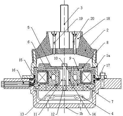
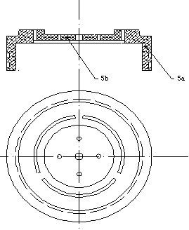
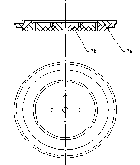
[0024] The present invention will be described in detail below in conjunction with accompanying drawing, as Figure 1-4 Shown: The engine magneto-rheological hydraulic mount based on the circumferential radial flow mode of the present invention includes a shell with an open top, a rubber main spring 2 arranged and blocked at the top opening of the shell, and a connection through the rubber main spring The rod 3 and the rubber bottom film 4 arranged at the inner bottom of the casing, the casing includes an upper casing 1a and a lower casing 1b connected by bolts, and the upper casing and the lower casing are both made of magnetic isolation aluminum alloy material A closed cavity filled with magneto-rheological fluid is formed between the rubber main spring and the rubber bottom film, and a magnetic core assembly is arranged in the cavity, and the magnetic core assembly includes an upper magnet from top to bottom. The core 5, the flowing coil seat 6 and the lower magnetic core 7...


PUM


Abstract

The invention discloses an engine magneto-rheological hydraulic mount method based on a circumferential and radial flowing mode. By means of the combination of a circumferential damping passageway and a radial damping passageway, the length of the damping passageways is increased in the limited structural size; the longer the damping passageways are, the larger the output damping force becomes; due to the fact that the amplitude of an engine is small, the maximum damping force can be increased by increasing the length of the damping passageways, and the adjustable range of the damping force can be widened; the width of the radial damping passageway is determined by the size of an insertion pin, and the width of the radial damping passageway can be changed by changing the size of the insertion pin; a liquid injection hole and an exhaust hole are formed in the middle of a reinforcing block, and therefore exhaust is more smooth in the liquid injection process, and liquid injection can be more convenient; a shell is made of magnetism isolation aluminum alloy material, and therefore magnetic flux leakage is weakened for a magnetic circuit when the engine works.

Description

technical field [0001] The invention relates to a vibration isolation device, in particular to an engine magneto-rheological hydraulic mount based on a circumferential radial flow mode. Background technique [0002] The viscosity and yield stress of magnetorheological fluid can change with the change of the external magnetic field, and this change has the characteristics of fast, reversible and controllable. Magneto-rheological hydraulic mount is to use the characteristics of magnetorheological fluid to change the output damping force of magnetorheological hydraulic mount by controlling the current in the excitation coil to change the magnetic field strength, so as to attenuate the vibration of the engine. The process responds quickly, the process is continuous and reversible. [0003] Existing magnetorheological hydraulic mounts based on flow patterns for vibration isolation of automobile engines have the following deficiencies: 1) Traditional magnetorheological hydraulic ...

Claims


Application Information

Patent Timeline
Patent Type & Authority Applications(China)
IPC IPC(8): F16F13/10B60K5/12
Inventor 郑玲张自伟邓召学郭敏敏
Owner CHONGQING UNIV
Why Eureka
Try Eureka