Solar-blind ultraviolet irradiation calibrating device

An external irradiation and calibration technology, applied in the field of ultraviolet radiation calibration, can solve the problems of low accuracy and narrow dynamic range of solar-blind ultraviolet testing, and achieve the effects of easy operation, highly automated testing process, and simple device structure.

Inactive Publication Date: 2014-10-01
CHANGCHUN INST OF OPTICS FINE MECHANICS & PHYSICS CHINESE ACAD OF SCI
View PDF4 Cites 10 Cited by
  • Summary
  • Abstract
  • Description
  • Claims
  • Application Information

AI Technical Summary

Problems solved by technology

[0004] In order to solve the problem of narrow dynamic range and low accuracy in the existing solar-blind ultraviolet test, the

Method used


Image

  • Solar-blind ultraviolet irradiation calibrating device
  • Solar-blind ultraviolet irradiation calibrating device

Examples


specific Embodiment approach 1

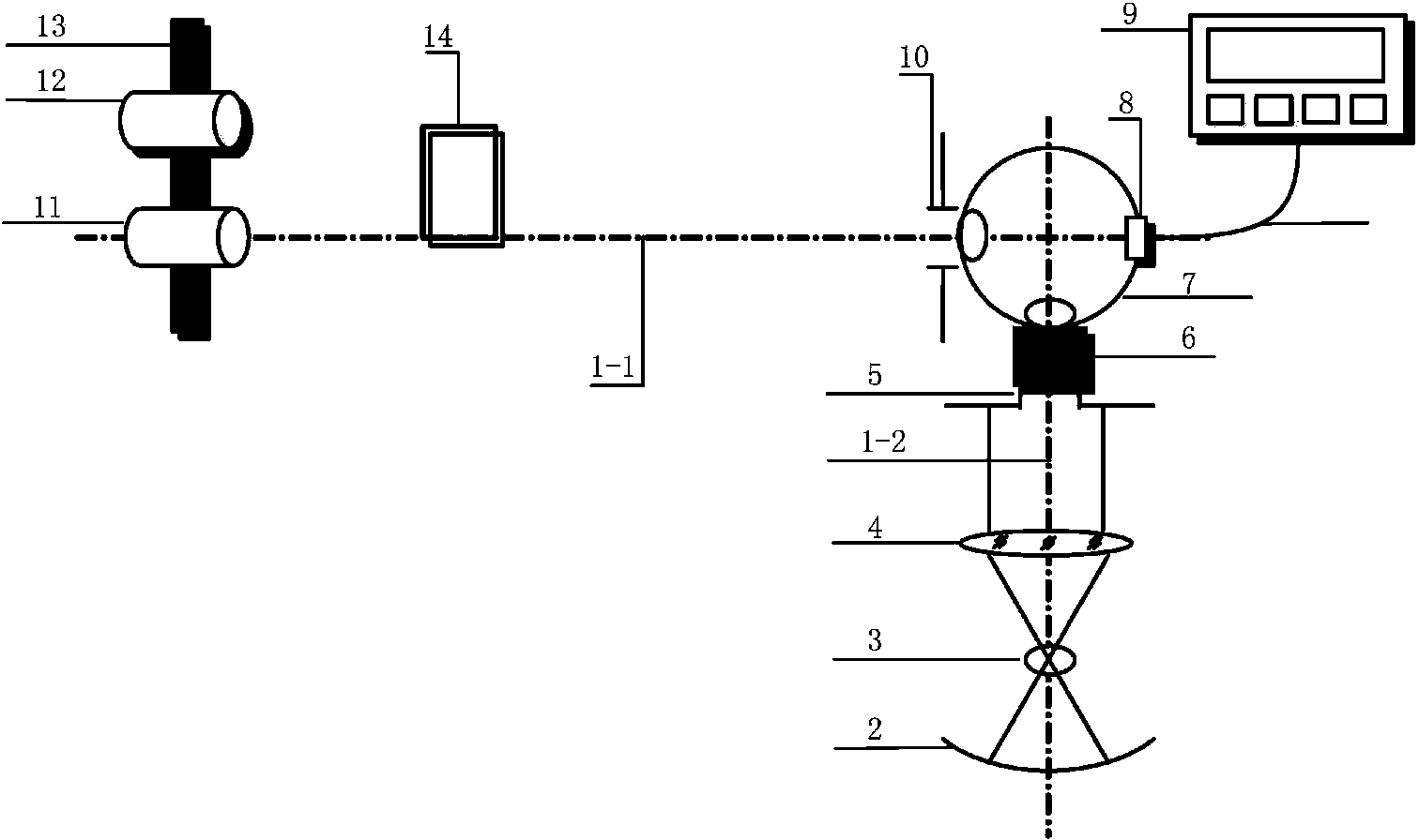
[0010] Specific implementation mode one, combination figure 1 In this embodiment, a large dynamic range solar-blind ultraviolet irradiance calibration device includes an optical track 1, which is L-shaped, and includes a main optical track 1-1 and a sub-optical track 1-2 perpendicular to each other, and the main optical track is 8m long. , Straightness≤±0.5mm, and the length of the secondary optical track is 2m. A condenser lens 2, an ultraviolet light source 3, a collimator lens 4, an entrance aperture 5 and a shielding cover 6 are sequentially installed on the secondary light track; the integrating sphere 7 is set at the vertical position of the main light track 1-1 and the secondary light track 1-2 . An exit aperture 10 and a horizontal electric displacement stage 13 are sequentially installed on the main optical track 1-1. The ultraviolet light source 3 is a highly stable ultraviolet deuterium lamp, which is used in conjunction with the condenser lens 2 and the collimator ...

specific Embodiment approach 2

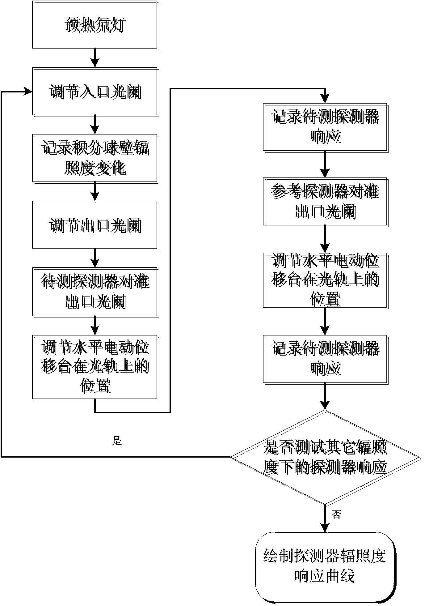
[0013] Specific implementation mode two, combination figure 2 This embodiment will be described. This embodiment is a method of using the solar-blind ultraviolet irradiance calibration device described in the first embodiment to test the irradiance response of a solar-blind ultraviolet detector, which has the following steps:

[0014] 1. Preheat the deuterium lamp for half an hour;

[0015] 2. Adjust the entrance aperture 5, and record the irradiance change of the inner wall of the integrating sphere 7 according to the reading of the weak current meter 9;

[0016] 3. Adjust the exit aperture 10;

[0017] 4. Mount the detector 11 to be tested on the horizontal electric translation stage 13 and adjust its position on the horizontal electric stage 13, and use the laser 14 to align the detector 11 to be measured at the center of the exit aperture 10;

[0018] 5. Adjust the position of the horizontal electric translation stage 13 on the main optical track 1-1 so that the distance between t...


PUM

PropertyMeasurementUnit
Outer diameteraaaaaaaaaa

Abstract

A solar-blind ultraviolet irradiation calibrating device relates to the field of ultraviolet irradiation calibration and solves the problems that existing solar-blind ultraviolet detection is narrow in dynamic range and low in accurate. The device comprises an L-shaped light track, an ultraviolet light source, an inlet diaphragm, a shielding cover, an integrating sphere, an outlet diaphragm, a silicon detector, a reference detector and a horizontal electric displacement bench, wherein the inlet diaphragm is used for controlling the radiation energy flux entering the integrating sphere, the shielding cover is used for shielding environmental stray light around the light source from entering the integrating sphere, the outlet diaphragm is tightly attached to an outlet of the integrating sphere and used for controlling the radiation energy flux of the outlet of the integrating sphere, the silicon detector is used for monitoring the irradiation change situation on the wall of the integrating sphere, the reference detector is used for measuring the irradiation at some position, and the horizontal electric displacement bench enables the reference detector and a detector to be detected to be arranged at the center of a light path in turns. The solar-blind ultraviolet irradiation calibrating device is simple in structure, strong in operability, high in accuracy and capable of achieving solar-blind ultraviolet detector irradiation calibration in a large dynamic range of 10-7 to 10-13W/cm<2>.

Description

Technical field [0001] The invention relates to the field of ultraviolet radiation calibration, in particular to the irradiance response calibration of solar-blind ultraviolet detectors in a large dynamic range. Background technique [0002] Solar-blind ultraviolet (240nm-280nm) imaging detection technology is used in corona discharge detection, missile approach warning, astronomical observation, medicine, biology and other fields because it is not interfered by the sun background noise and can achieve accurate imaging detection of weak ultraviolet targets. Has been widely used. [0003] As the core component of solar-blind ultraviolet imaging detection, it is very important to understand its response characteristics under different irradiance fields. At present, there are few research reports on the calibration of solar-blind ultraviolet irradiance in China, and the test dynamic range of related devices is narrow and the stability is low, which is not enough to meet the requireme...

Claims


Application Information

Patent Timeline
IPC IPC(8): G01M11/02
Inventor 陈雪闫丰章明朝周跃李佩玥易翔宇杨怀江隋永新
Owner CHANGCHUN INST OF OPTICS FINE MECHANICS & PHYSICS CHINESE ACAD OF SCI
Why Eureka
Try Eureka