Projection optical engine

A technology of projection optics and engine, which is applied in the field of projection optical engine, can solve the problems of small light source area of ​​light-emitting diodes, insufficient output brightness of projectors, limited light collection ability, etc., and achieves easy installation and arrangement of heat dissipation and air duct devices, and compact structure , the effect of small space size

Inactive Publication Date: 2014-10-08
SHENZHEN HUOLE TECH DEV CO LTD
View PDF8 Cites 8 Cited by
  • Summary
  • Abstract
  • Description
  • Claims
  • Application Information

AI Technical Summary

Problems solved by technology

[0004] For projectors that use light-emitting diodes as light sources, technically speaking, their output brightness is limited by the size of the light-emitting area and luminous power of the light source, and the above two are closely related to the size of the digital micromirror display chip, but the area of ​​the light-emitting diode light source is small The output power is relatively low, and the overall output brightness of the projector is insufficient. If the output power of the light-emitting diode is to be increased, the light-emitting area must be large. When it is large to a certain extent, it will not match the size of the digital micromirror display chip. The problem caused is that the light of the light-emitting unit of the light-emitting diode away from the central part can either not be irradiated on the digital micromirror display chip to form the light of the illuminated image, or can enter the digital micromirror display chip but cannot be detected because the incident angle is too large. Collected into the projection lens and projected out. In this way, the output brightness of the system is determined by the size of the light emitting diode and the level of light density. With the progress of integrated packaging technology, some companies at home and abroad have specially developed a series of high Density surface-emitting integrated packaged light-emitting diode modules are used in projector systems. If these light-emitting diode modules are to be well matched with digital micromirror display chips, and to achieve efficient use of light and relatively high output brightness , it is still necessary to design a special optical collimator, focusing and uniform light system, and a color synthesis system, combined with the design of a matching projection lens; conventionally, if a compound lens is used as a light homogenization and shaping device, relatively large For LED modules with a large light-emitting area, the ability to collect light is limited due to the large off-axis of light; light, but to ensure that most of the light passes through the entire projection system, it is still necessary to design a reasonable lighting path and a matching projection lens to achieve

Method used


Image

  • Projection optical engine
  • Projection optical engine
  • Projection optical engine

Examples


Embodiment Construction

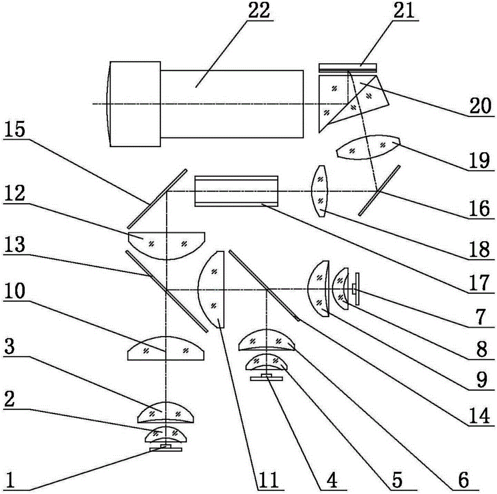
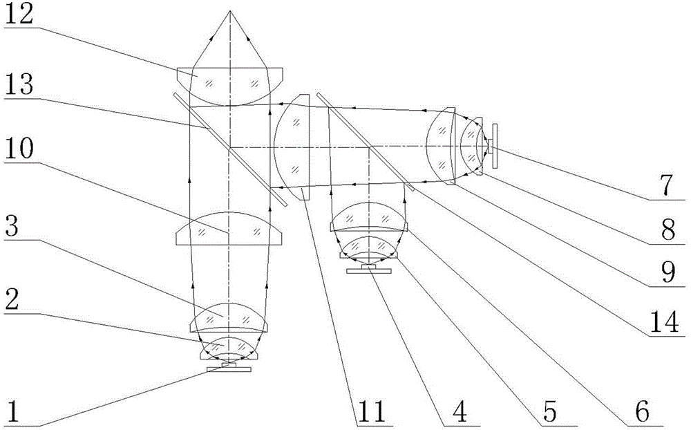
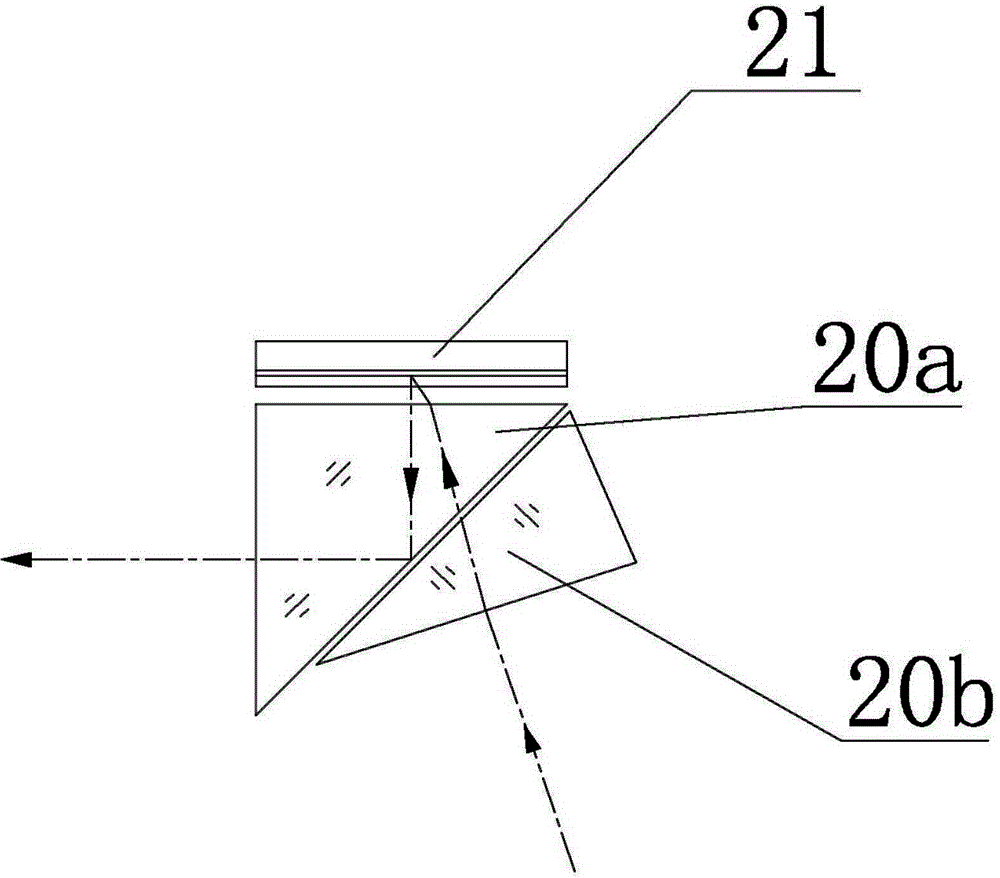
[0036] Such as figure 1 As shown, the projection optical engine proposed by the present invention includes: a first turning mirror 15, a light guide rod 17, a first relay lens 18, and a second turning mirror 16 arranged horizontally and sequentially; A light source is provided, and the top of the first turning reflector 15 is inclined towards the light source near the light guide rod 17, and the bottom is inclined; Display chip 21, the incident surface of total reflection prism 20 is inclined towards the second turning mirror 16, the second relay lens 19 is inclined and the angle of inclination matches the incident surface of total reflection prism 20, the second turning mirror 16 bottom Near the first relay lens 18, the top is inclined towards the incident surface of the total reflection prism 20, and the working surface of the digital micromirror display chip 21 is parallel to the outer surface of the total reflection prism 20 and towards the total reflection surface of the ...


PUM


Abstract

The invention discloses a projection optical engine. The projection optical engine comprises a first turning reflector, a light guide stick, a first relay lens and a second turning reflector which are horizontally arranged in sequence, wherein a light source is arranged below the first turning reflector; the projection optical engine further comprises a second relay lens, a total-reflection prism and a digital micromirror display chip which are arranged above the second turning reflector in sequence; the incidence surface of the total-reflection prism is inclined towards the second turning reflector; the second relay lens is inclined, and the inclination angle of the second relay lens is matched with the incidence surface of the total reflection prism; the bottom end of the second turning reflector is close to the first relay lens, and the top end of the second turning reflector is inclined towards the incidence surface of the total-reflection prism; the working surface of the digital micromirror display chip is parallel to the outer side surface of the total-reflection prism and faces the total reflection surface of the total-reflection prism; a projection lens is arranged on the outer side of the emergency surface of the total-reflection prism. The projection optical engine provided by the invention is reasonable in function layout and compact in structure, and can realize high-efficiency light utilization and high-brightness light output.

Description

technical field [0001] The invention relates to a projection optical engine. Background technique [0002] Traditional projectors using metal halide or high-pressure mercury lamp bulbs are limited in their home applications due to defects such as short life of the bulb, large radiation caused by high-voltage drive, long switching time delay, high power consumption, and high noise; Light-emitting diodes have technical characteristics such as long life, no radiation in drive control, low power consumption, fast response, rich color combinations, etc., and the light-emitting diode industry has developed rapidly with the huge market demand of the lighting market and automotive lamps market, especially light-emitting diodes. With the rapid progress of integrated semiconductor-level packaging technology, it has become a trend to gradually replace the traditional metal halide or high-pressure mercury bulb light source of the projector. The technology of using light-emitting diodes ...

Claims


Application Information

Patent Timeline
Patent Type & Authority Applications(China)
IPC IPC(8): G03B21/20G03B21/14G03B21/16
Inventor 张建平
Owner SHENZHEN HUOLE TECH DEV CO LTD
Why Eureka
Try Eureka