
A Control Loop System for Multi-mode Digital Switching Power Supply

A digital switching power supply, multi-mode switching technology, applied in electrical components, output power conversion devices, etc., can solve the problem of not eliminating the two-mode jumping back and forth, output voltage fluctuations, etc.

Active Publication Date: 2016-08-17
SOUTHEAST UNIV
View PDF5 Cites 1 Cited by
  • Summary
  • Abstract
  • Description
  • Claims
  • Application Information

AI Technical Summary

Problems solved by technology

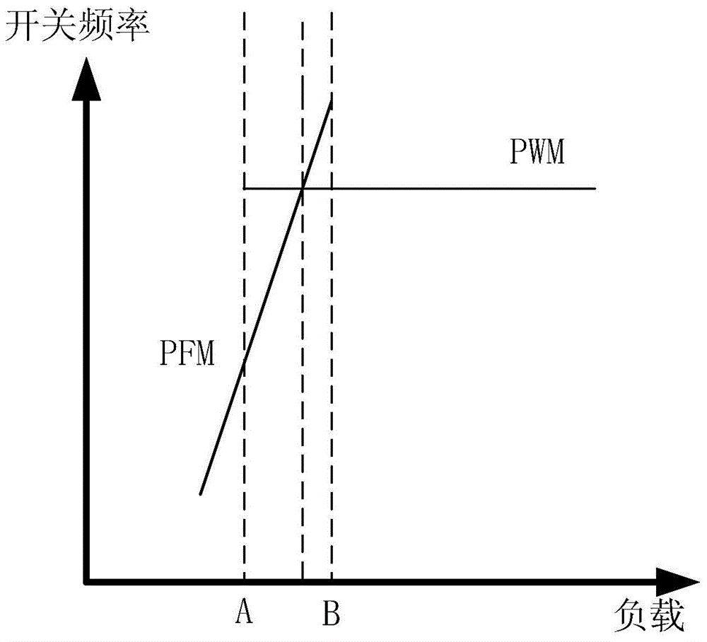
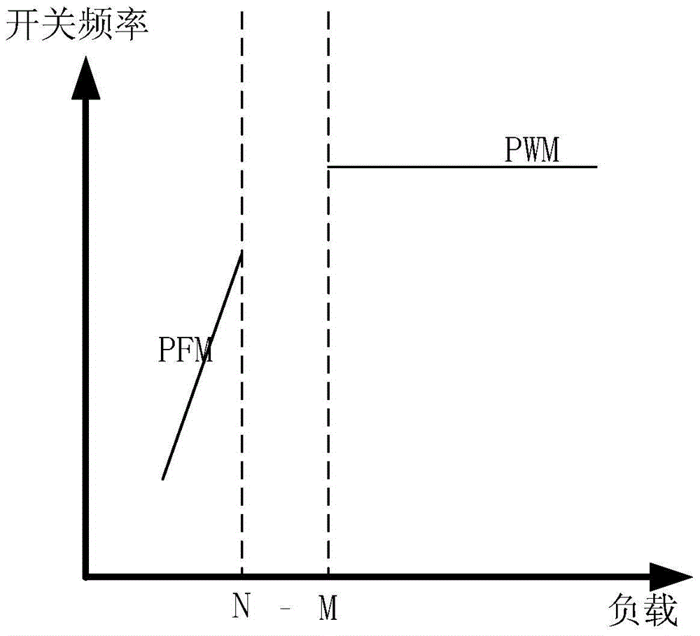
When the load is between M and N, the system will switch back and forth between the two modes. The switching condition is that the output voltage is greater than or less than the set limit, but this scheme does not eliminate the back and forth between the two modes. jump, the output voltage still has a certain fluctuation

Method used


Image

  • A Control Loop System for Multi-mode Digital Switching Power Supply
  • A Control Loop System for Multi-mode Digital Switching Power Supply
  • A Control Loop System for Multi-mode Digital Switching Power Supply

Examples


Embodiment Construction

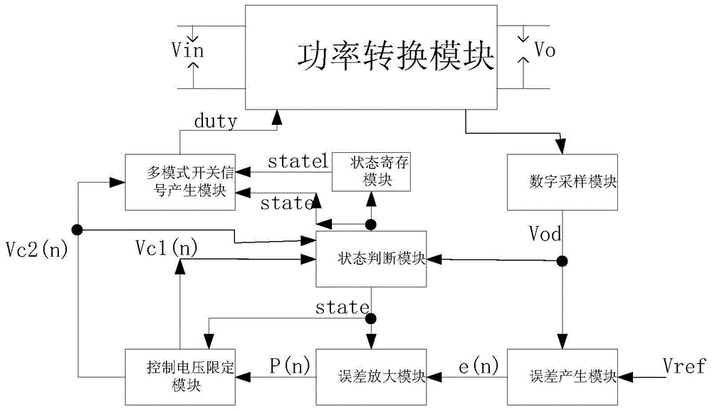
[0055] see image 3 and Figure 4 , the control system for the multi-mode digital switching power supply of the present invention includes a digital sampling module, an error generation module, a state registration module, a state judgment module, an error amplification module, a control voltage limiting module and a control loop composed of a multi-mode switching signal generation module system, the control loop system and the controlled power converter form a closed loop; during the turn-on period of the power converter switch tube in this cycle, the multi-mode switch signal generation module controls the The voltage Vc2(n-1) is calculated to obtain the switch conduction time of this cycle and the switching frequency of this cycle, and then the digital sampling module collects the output voltage signal of the controlled power converter and converts it into a digital signal Vod and outputs it to the error generation module at the same time And the state judging module, the s...


PUM


Abstract

A control loop system for a multi-mode digital switching power supply, including a digital sampling module, an error generation module, a state register module, a state judgment module, an error amplification module, a control voltage limiting module and a multi-mode switch signal generation module, the digital sampling The module collects the controlled signal and converts it into a digital signal Vod. The state judgment module judges the state value state that the control loop system needs to enter according to the trigger condition of the state transition. The error amplifier generates the control value P(n) according to the error signal e(n). The control quantity P(n) enters the control voltage limiting module, and the control voltage limiting module obtains the corresponding control voltages Vc1(n) and Vc2(n) according to the state value state and P(n) of the control loop system at this time, multi-mode The switching signal generating module obtains a duty ratio signal according to Vc2(n) and the state value state, and controls the conduction of the switching tube of the controlled power converter.

Description

technical field [0001] The invention relates to a digital switching power supply, in particular to a control loop system for a multi-mode digital switching power supply. Background technique [0002] With the development of digital technology, digital power supply has been paid more and more attention due to its own advantages. In AC-DC and DC-DC switching power supply, more and more control systems are realized in digital way, but with the global energy In short supply, the United States VI energy efficiency standard has higher and higher requirements for power conversion efficiency. Now it is imminent to realize a switching power supply with high efficiency in the whole load range. At light load, switching loss accounts for most of the energy loss of the entire system. The direct way to reduce switching loss at this time is to reduce the switching frequency. Based on this consideration, many digital power supplies now adopt multi-mode control schemes. At heavy load, the s...

Claims


Application Information

Patent Timeline
Patent Type & Authority Patents(China)
IPC IPC(8): H02M1/08
Inventor 徐申程松林范献军钱钦松孙伟锋陆生礼时龙兴
Owner SOUTHEAST UNIV
Learn More