Mechanical catapult for carrier-based aircraft

A technology of catapults and carrier-based aircraft, which is applied in the direction of launching/dragging transmissions, etc., can solve the problems of high cost of use and manufacturing, difficulty in mastering sealing technology, and complicated manufacturing process, and achieve energy saving, low maintenance and operation costs, Ejection safe and reliable effect

Inactive Publication Date: 2014-10-15
吴炳选
View PDF4 Cites 7 Cited by
  • Summary
  • Abstract
  • Description
  • Claims
  • Application Information

AI Technical Summary

Problems solved by technology

[0003] Although the steam catapult has 50 years of mature use technology, its use cost and manufacturing cost are high. Each ejection requires 1 ton of fresh water, and seawater desalination devices, water storage tanks, gas storage tanks, boilers and other facilities are required, especially the manufacturing process. Complicated, difficult to master the sealing technology, weighing more than 500 tons, taking up a lot of space, etc.

Method used


Image

  • Mechanical catapult for carrier-based aircraft
  • Mechanical catapult for carrier-based aircraft
  • Mechanical catapult for carrier-based aircraft

Examples


Embodiment Construction

[0030] The present invention will be further described below in conjunction with the accompanying drawings.

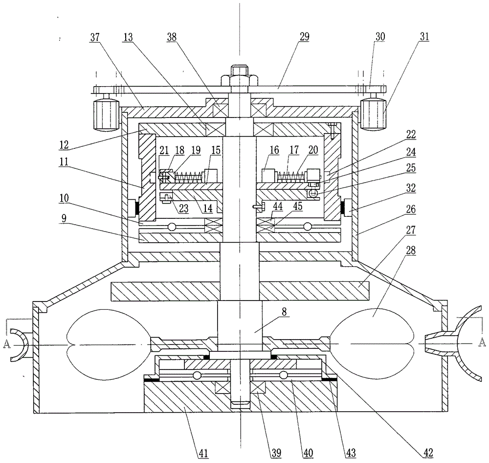
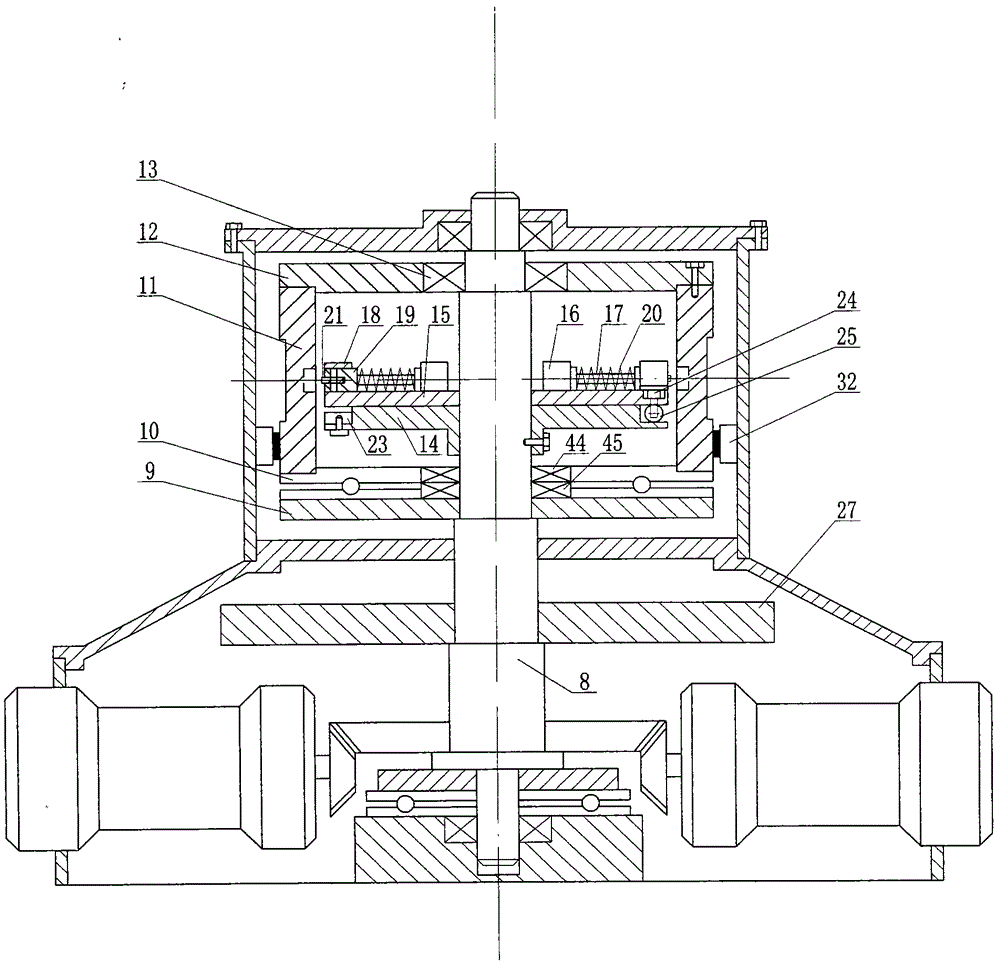
[0031] The present invention mainly describes two kinds of power, that is: a catapult powered by a water turbine and a gas turbine. Bracing frame 37 and power transmission shaft supporting frame bearing 38 are connected on the housing 26, and the lower end is fixed on the base 41 by base bearing 39 and base plane thrust bearing 40, and sealing cover 42 is sealed on the base with sealing ring 43 to prevent the bearing from entering water. Such as figure 1 Figure 7 shown.

[0032] 1. Ejection implementation mode powered by water turbine

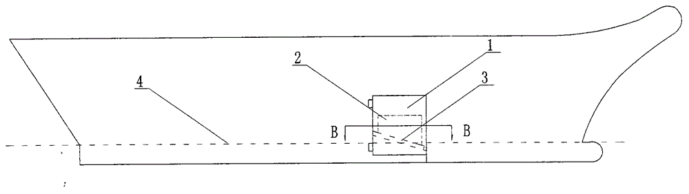
[0033] 1. The power generation process of the water turbine: with the water turbine as the ejection power, the seawater as the thrust must first be introduced into the water turbine. There are two ways to introduce it, namely: dynamic water inlet and static water inlet.

[0034] The dynamic water intake method is: the water inlet 1...


PUM


Abstract

The invention discloses a mechanical catapult for carrier-based aircraft. The mechanical catapult comprises a transmission shaft, a winch, clutches, brakes, a flywheel, a wire rope, a runway, and a slide. The mechanical catapult is technically characterized in that except the brakes disposed on a housing and the runway and the slide both disposed on a deck, the rest are all disposed on the transmission shaft; two trays are disposed on the transmission shaft and include one which supports a winch assembly and the other which supports the clutches. The winch assembly is braked to stop rotating, the clutches rotate in the center of the winch along with the transmission shaft, engaging-disengaging sliders are inserted into connections of the winch before catapulting, the winch is driven to rotate with the transmission shaft so as to wind the wire rope onto the winch, and the slide is pulled to drive an aircraft to take off. Catapulting powers are various; a water turbine and a gas turbine are taken as examples in the invention; when the water turbine is used as a power source, water is driven in by self-power of an aircraft carrier through an inflow gate, or a high-pressure water pump is driven by a motor, a diesel engine or the like to impact an impeller, and power is generated; when the gas turbine is used as a power source, power is transmitted to the transmission shaft through a reducer so that catapulting is available.

Description

technical field [0001] The invention relates to a launch device for carrier-based aircraft designed by using the principle of a hydroelectric generator. Its stator is similar to the winch of the launch device, and its rotor is similar to a clutch rotating in the middle of the winch. When the two are combined, the winch winches A catapult device in which the shuttle in the slideway is pulled by a wire rope to drive the aircraft to take off. It imitates the umbrella-shaped vertical design of the Three Gorges hydroelectric generator, and uses the mechanical power generated by the hydroturbine to eject. More specifically, it is a mechanical ship Carrier catapult. Background technique [0002] At present, the only mature ejection technology in the world is the steam catapult of the United States, and the electromagnetic catapult is still in the experimental stage. As for the flywheel energy storage catapult tested by the United States in the 1940s, it was abandoned because the cl...

Claims


Application Information

Patent Timeline
Patent Type & Authority Applications(China)
IPC IPC(8): B64F1/06
Inventor 吴炳选
Owner 吴炳选
Why Eureka
Try Eureka