Heat accumulating type dividing-wall heating industrial furnace

An industrial kiln and regenerative technology, which is applied in the field of industrial shaft kilns and industrial kilns with regenerative partition heating, can solve the problem of inability to recover carbon dioxide, unutilized exhaust flue gas, and low preheating temperature of combustion-supporting air. and other problems to achieve the effect of improving comprehensive economic benefits, reducing energy consumption and reducing exhaust emissions

Active Publication Date: 2014-10-29
SHIJIAZHUANG XINHUA IND FURNACE CO LTD
View PDF5 Cites 6 Cited by
  • Summary
  • Abstract
  • Description
  • Claims
  • Application Information

AI Technical Summary

Problems solved by technology

This patent solves the problems of unutilized flue gas from the lime kiln, waste of heat energy, high fuel consumption, and low preheating temperature of combustion-supporting air, but this patented technology cannot solve the problem of recycling carbon dioxide in lime production

Method used


Image

  • Heat accumulating type dividing-wall heating industrial furnace
  • Heat accumulating type dividing-wall heating industrial furnace
  • Heat accumulating type dividing-wall heating industrial furnace

Examples


Embodiment 1

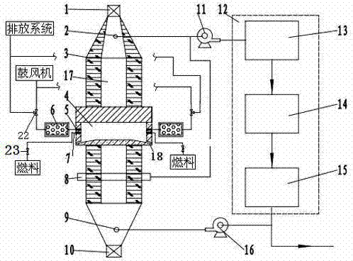
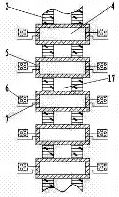
[0016] The industrial furnace kiln of the present invention heat storage type partition heating such as figure 1 , figure 2 As shown, a vertical kiln and a carbon dioxide treatment unit 12 are included. The vertical kiln is provided with a material inlet 1, a material outlet 10, a decomposition gas outlet 2 and a cooling air inlet 9. The carbon dioxide processing unit is provided with a carbon dioxide purification device 13, a carbon dioxide cooling device 14 and a carbon dioxide storage tank 15, and the carbon dioxide purification device, the carbon dioxide cooling device and the carbon dioxide storage tank are connected in sequence. The decomposition gas outlet is connected to the carbon dioxide processing unit through the induced draft fan 11, the cooling air inlet is connected to the outlet of the cooling fan 16, and the inlet of the cooling fan is connected to the carbon dioxide storage tank. The kiln chamber 17 of the lime kiln is provided with a preheating zone, a ca...

Embodiment 2

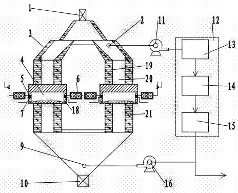
[0019] Another embodiment of the present invention is an annular kiln, such as image 3 , Figure 4 As shown, it is composed of an inner ring 19 and an outer ring 21, and the annular space 20 between the inner ring and the outer ring is a kiln chamber for processed materials. The 8 combustion chambers are evenly distributed across the inner ring, annular space and outer ring. Regenerators 6 are arranged on both sides of each combustion chamber, and the air ports on both sides of the combustion chamber are respectively connected with the regenerators. The heat accumulator on the outside of the combustion chamber preheats the combustion air, the fuel nozzles on the outside of the combustion chamber (outside the outer ring) spray fuel for combustion, and the generated flue gas is stored in the heat accumulator 6 inside the combustor chamber (inside the inner ring). Then reversing the fuel outlet inside the combustor chamber to spray fuel for combustion, the regenerator in the r...


PUM


Abstract

The invention relates to a heat accumulating type dividing-wall heating industrial furnace including a lime kiln and a carbon dioxide processing unit; the lime kiln is provided with a feed port, a discharge port, a decomposition gas outlet and a cooling air inlet. The decomposition gas outlet is connected with the carbon dioxide processing unit through a draught fan, and an inlet of a cooling fan is connected with the carbon dioxide processing unit or is communicated with the atmosphere. A calcining zone of the lime kiln is provided with combustion chambers, and the walls of the combustion chambers are formed by constructing heat conduction brick masonry or are made of a metal material. An air port of each combustion chamber is connected with a heat accumulator, and the other end of each heat accumulator is connected with an air blower and a draindown system through a three-way valve. A cooling zone is provided with a lower suction beam, and an outlet of the lower suction beam is connected to the drought fan or a fuel preheater. With additional arrangement of the combustion chambers and the heat accumulators, a material in a kiln body is heated through the heat conduction brick masonry in a flame isolation mode, high-purity carbon dioxide is facilitated to be recycled, combustion-supporting air is preheated by flue gas, the combustion-supporting air temperature is increased, heat energy resources are fully utilized, and the energy consumption of the lime kiln is reduced.

Description

technical field [0001] The invention belongs to the technical field of calcining equipment, and relates to an industrial shaft kiln, in particular to an industrial furnace kiln with regenerative partition heating. Background technique [0002] The recovery and utilization of industrial furnace waste heat can save energy consumption, reduce the production cost of thermal products, and reduce the emission of pollutants. Industrial furnaces are large-scale high-energy-consuming devices. With the rapid development of the national economy, the waste heat of industrial furnaces is very rich and has great potential for utilization. Iron and steel industry, calcium carbide industry, alumina industry and refractory material industry are major energy consumers. The rapid growth of the above industries has driven the rapid development of industrial furnaces. During the production process of thermal products, the flue gas discharge temperature is high, about 240-360°C. Effective use o...

Claims


Application Information

Patent Timeline
Patent Type & Authority Applications(China)
IPC IPC(8): C04B2/10C04B2/12C01B31/20C01B32/50
CPCY02P20/129Y02P40/40
Inventor 贾会平
Owner SHIJIAZHUANG XINHUA IND FURNACE CO LTD
Why Eureka
Try Eureka