A sewage treatment device using continuous biofilm method and its operation process

The technology of a sewage treatment device and operation process, which is applied in the field of sewage biotechnology treatment, can solve the problems of increasing the technological process and difficulty of operation and management of aerated biological filters, unfavorable denitrification by denitrifying bacteria, and increasing carbon dioxide emissions. Small footprint, reduced pipe laying, and the effect of reducing hydraulic resistance

Active Publication Date: 2016-03-09
海若斯(北京)环境科技有限公司
View PDF6 Cites 0 Cited by
  • Summary
  • Abstract
  • Description
  • Claims
  • Application Information

AI Technical Summary

Problems solved by technology

[0003] However, the biological aerated filter process has high requirements on the quality of the influent water. If the content of suspended solids (SS) in the influent water is too high, the SS and biomass in the tank will increase rapidly, which will increase the resistance of the filter tank, thereby increasing the The frequency of backwashing to keep the biological aerated filter running properly
At present, the solution to this problem is usually to add a pretreatment process before the biological aerated filter, which not only greatly increases the difficulty of the process flow and operation management of the biological aerated filter, but also removes a large amount of The chemical oxygen demand (COD) reduces the content of organic matter entering the biological aerated filter, which is not conducive to the denitrification of denitrifying bacteria. It is often necessary to add carbon sources to supplement the nutrients of denitrifying bacteria, which not only increases the running time costs, while also significantly increasing carbon dioxide emissions

Method used


Image

  • A sewage treatment device using continuous biofilm method and its operation process
  • A sewage treatment device using continuous biofilm method and its operation process

Examples


Embodiment 1

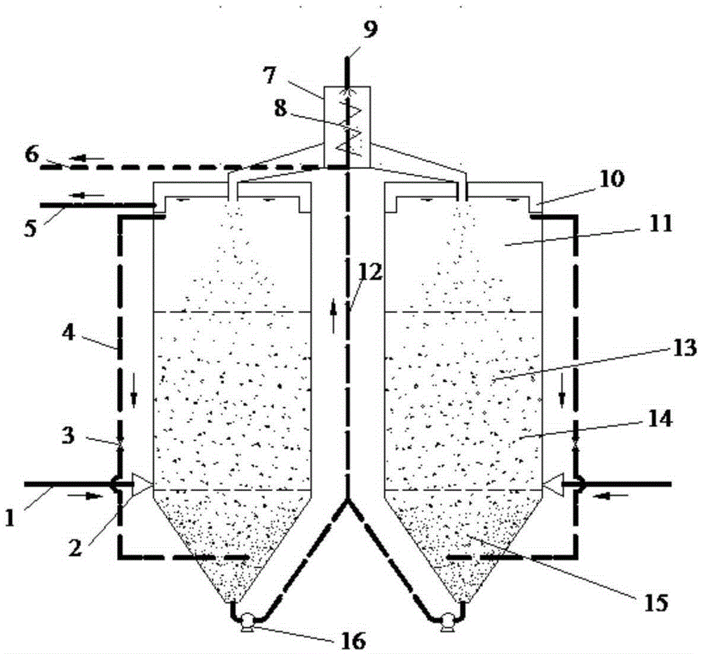
[0022] A sewage treatment device using a continuous biofilm method designed by the present invention includes a water inlet system 1, an aeration system 2, a denitrification system 4, a cleaning system 7 and an integrated biofilm reactor; the integrated biological The membrane reactor is filled with a porous wear-resistant biofiller 14 with a particle size of 4mm; the integrated biofilm reactor is divided into a denitrification zone 15, a nitrification zone 13 and a clean water zone 11 from bottom to top, and the nitrification zone 13 and the denitrification zone The effective volume ratio of 15 is 4:1; the top of the clean water zone 11 is provided with a water outlet tank 10 with a water outlet pipe 5; Its water outlet is set in the denitrification zone 15, and the opening and closing are controlled by the valve 3; the aeration system 2 is connected with the water inlet system 1, and the sewage is pumped into the integrated biofilm reactor through the water inlet system 1 and...

Embodiment 2

[0031] A sewage treatment device using a continuous biofilm method designed by the present invention includes a water inlet system 1, an aeration system 2, a denitrification system 4, a cleaning system 7 and an integrated biofilm reactor; the integrated biological The membrane reactor is filled with a porous wear-resistant biofiller 14 with a particle size of 3mm; the integrated biofilm reactor is divided into a denitrification zone 15, a nitrification zone 13 and a clean water zone 11 from bottom to top, and the nitrification zone 13 and the denitrification zone The effective volume ratio of 15 is 8:1; the upper part of the clean water zone 11 is provided with a water outlet tank 10 with a water outlet pipe 5; Its water outlet is set in the denitrification zone 15, and the opening and closing are controlled by the valve 3; the aeration system 2 is connected with the water inlet system 1, and the sewage is pumped into the integrated biofilm reactor through the water inlet syste...

Embodiment 3

[0040] A sewage treatment device using a continuous biofilm method designed by the present invention includes a water inlet system 1, an aeration system 2, a denitrification system 4, a cleaning system 7 and an integrated biofilm reactor; the integrated biological The membrane reactor is filled with a porous wear-resistant biofiller 14 with a particle size of 5mm; the integrated biofilm reactor is divided into a denitrification zone 15, a nitrification zone 13 and a clean water zone 11 from bottom to top, and the nitrification zone 13 and the denitrification zone The effective volume ratio of 15 is 8:1; the upper part of the clean water zone 11 is provided with a water outlet tank 10 with a water outlet pipe 5; Its water outlet is set in the denitrification zone 15, and the opening and closing are controlled by the valve 3; the aeration system 2 is connected with the water inlet system 1, and the sewage is pumped into the integrated biofilm reactor through the water inlet syste...


PUM

PropertyMeasurementUnit
particle diameteraaaaaaaaaa

Abstract

The invention relates to a sewage processing apparatus employing a continuous biofilm method and an operation technology thereof. The apparatus comprises a water intake system, an aerating system, a denitrification nitrogen-removal system, a cleaning system and an integrated biofilm reactor; the integrated biofilm reactor is divided into a denitrification zone, a nitrification zone and a clean water zone from bottom to top; a water inlet of the denitrification nitrogen-removal system is arranged in the clean water zone, and a water outlet is arranged at the denitrification zone; the aerating system is connected with the water intake system, sewage is pumped into the integrated biofilm reactor via the water intake system, and the aerating system oxygenates sewage; the cleaning system comprises a material lifting pipe, a material lifting pump and a material cleaning device; and the material cleaning device is arranged on the integrated biofilm reactor, and is inside provided with a material-cleaning sewage discharging pipe, a spiral propeller and a material-cleaning water pipe. Compared with the prior art, the apparatus overcomes the disadvantage that intermittent water injection is carried out when a biological aerated filter is subjected to backwashing, requirement on inlet water quality is reduced, and the apparatus has reinforced denitrification function without adding a carbon source.

Description

technical field [0001] The invention belongs to the field of biological treatment of sewage, and in particular relates to a sewage treatment device adopting a continuous biofilm method and an operating process thereof. Background technique [0002] Biological aerated filter is a typical biofilm treatment method. In the late 1980s and early 1990s, a new type of sewage treatment process was developed on the basis of ordinary biological filters, which integrated the strong oxidative degradation ability of the biofilm and the interception and adsorption efficiency of the filter layer, and played a role in the process. The role of ordinary aeration tanks, secondary sedimentation tanks and sand filters. This treatment method has multiple functions such as intercepting SS, removing organic matter, and removing nitrogen and phosphorus. Its advantages such as strong impact load resistance, high volume load, small footprint, and low sludge output make it have a broad application pros...

Claims


Application Information

Patent Timeline
Patent Type & Authority Patents(China)
IPC IPC(8): C02F3/00
Inventor 孙开瑄王敏王焕升苏本生宋英豪孙慧敏徐晶崔志峰
Owner 海若斯(北京)环境科技有限公司
Why Eureka
Try Eureka