Precise cold forging formed cam sheet manufacturing method

A manufacturing method and technology of cam sheets, which are applied in mechanical equipment, engine components, metal processing equipment, etc., can solve the problems of harsh operating environment, complex equipment and large deformation of warm forging, and improve fatigue strength and stress corrosion resistance. capacity, reduced equipment investment and parts costs, the effect of reduced average stress levels

Active Publication Date: 2014-11-19
HANGZHOU XZB TECH
View PDF7 Cites 8 Cited by
  • Summary
  • Abstract
  • Description
  • Claims
  • Application Information

AI Technical Summary

Problems solved by technology

The disadvantages of the hot forging process are: 1. Once the temperature exceeds the phase transition temperature, the local structure of the part will be transformed, or even hardened, and there is a risk of cracking
The disadvantages of the warm forging process are: 1. The material needs to be heated, the equipment is more complicated, and the cost is high
2. The operating environment of warm forging is relatively harsh
3. In warm forging, due to the use of induction heating, it is difficult to control the temperature. Under equipment debugging and low speed, the material may be heated beyond the phase transition te

Method used


Image

  • Precise cold forging formed cam sheet manufacturing method
  • Precise cold forging formed cam sheet manufacturing method
  • Precise cold forging formed cam sheet manufacturing method

Examples


Embodiment 1

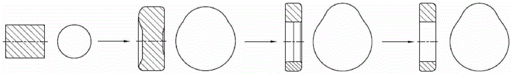
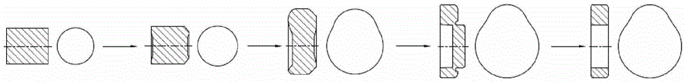
[0056] Such as Figure 5 As shown, the cam piece is made of high-carbon bearing steel or combined steel wire or bar steel after annealing, drawing and lubrication to make it suitable for cold forging; See Figure 5 ) to extrude the final profile of the cam piece; then the forging is subjected to stress annealing (or spheroidizing annealing); finally, it undergoes another extrusion shaping to meet the final size requirements.

[0057] A method for manufacturing a precision cold forging cam plate, comprising the following steps:

[0058] A. Pretreatment step, the wire or bar steel is annealed, drawn and lubricated to make it suitable for the first blank formed by cold heading;

[0059] B. Cold forging forming step, using a horizontal or vertical forging press to forge the cam piece;

[0060] C. Heat treatment;

[0061] Wherein, the cold forging forming step includes an expanding extrusion process.

[0062] Optimally, the cold forging forming step consists of the following o...

Embodiment 2

[0073] The utility model relates to an extrusion punch used in the manufacturing method of a precision cold forging cam sheet, and its front end is a tapered head.

[0074] Optimally, both ends of the extrusion punch are tapered, the diameter of the bottom surface of the tapered head is smaller than the diameter of the through hole in the middle of the cam plate, and the diameter of the bottom surface of the tapered bottom is consistent with the diameter of the through hole in the middle of the cam plate.


PUM


Abstract

The invention relates to a precise cold forging formed cam sheet manufacturing method. The manufacturing method includes the steps of A, pretreatment, B, cold forging forming and C, thermal treatment, wherein in the step A, a steel wire rod or a steel bar is annealed, drawn and lubricated, so that a first blank suitable for cold upsetting forming is obtained; in the step B, a cam sheet is forged through a horizontal or vertical forging machine, and the cold forging forming step includes an expansion and extrusion procedure. Due to the adoption of the expansion and extrusion technology, acquisition of a ball bearing steel cold forging cam is possible for the first time; compared with the traditional upsetting technology, forging force is greatly reduced, the cold hardening speed is low, cracks are not likely to generate, the service life of a die is greatly prolonged, a metallographic structure can not be changed in the cold forging process, and a surface structure is free of the carbon insufficiency risk; due to the fact that a finally-used outline is obtained through precise extrusion or finishing directly, the outline of the cam does not need to be ground, and equipment investment and part cost are greatly reduced.

Description

technical field [0001] The invention relates to a method for manufacturing a precision cold forging cam piece. Background technique [0002] In recent years, with the enhancement of people's awareness of low-carbon environmental protection, low fuel consumption, no pollution, light weight, and low-cost engine models have attracted more and more attention. In order to reduce automobile exhaust emission pollution, low fuel consumption, and realize high speed and high output power of the engine, many engines adopt a structure with multiple valves, valve timing, and variable valve lift. At the same time, in order to achieve the goal of light weight and low cost of automobiles, the processing of parts should be simplified as much as possible, the weight should be reduced, and the use of materials should be more reasonable without affecting the performance of each part. And with the adoption of engine turbocharging and direct injection technology, the degree of strengthening of t...

Claims


Application Information

Patent Timeline
IPC IPC(8): B21K3/00B21J5/02B21J5/06B21J5/08B21J5/10C21D7/10C21D1/26
Inventor 徐纳
Owner HANGZHOU XZB TECH
Why Eureka
Try Eureka