A self-lubricating bearing plate sintering method and a plate rack used for the method

A self-lubricating bearing and plate frame technology, applied in the field of metal sintering, can solve the problems of inability to guarantee the heat distribution between layers and the uniformity of sintering atmosphere, reduce the performance of sintered products, and unstable sintering quality, so as to improve production quantity and efficiency Improvement, the effect of reasonable structure size

Active Publication Date: 2016-10-19
江苏立一新材料科技有限公司
View PDF6 Cites 0 Cited by
  • Summary
  • Abstract
  • Description
  • Claims
  • Application Information

AI Technical Summary

Problems solved by technology

[0005] Due to the high environmental requirements for sintering of self-lubricating bearing plates, the existing technology is generally single-layer sintering. The production quantity per unit time of this method is low, and it cannot reach a high processing capacity in a short period of time. In order to improve efficiency, there are The manufacturer came up with a method of using galvanized steel sheets as the isolation layer between the layers of copper-plated metal sheets to achieve multi-layer sintering. However, due to the close combination of self-lubricating bearing sheets and galvanized steel sheets during the sintering process, the layer-to-layer gap cannot be guaranteed. The indirect heat distribution and the uniformity of the sintering atmosphere reduce the performance of the sintered product and basically cannot be applied
[0006] Therefore, it is urgent to invent a device for sintering of multi-layer self-lubricating bearing plates to solve the problems of low sintering efficiency and unstable sintering quality of existing self-lubricating bearing plates

Method used


Image

  • A self-lubricating bearing plate sintering method and a plate rack used for the method
  • A self-lubricating bearing plate sintering method and a plate rack used for the method
  • A self-lubricating bearing plate sintering method and a plate rack used for the method

Examples


Embodiment 1

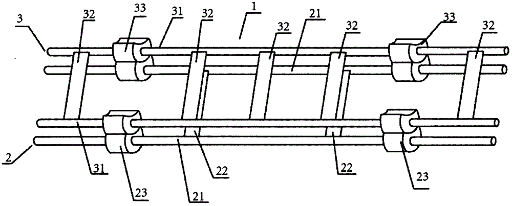
[0039] See attached Figure 1-2 , a self-lubricating bearing plate sintering plate rack 1, including a plate layer 2, a plate layer 3; the plate layer 2 includes two support rods 21 and two connecting rods 22; the two support rods Both ends are covered with fixing parts 23; all fixing parts are in the shape of a cylinder, and the surface is provided with a concave surface 231 with an upward opening;

[0040] Described putting board layer 3 comprises two support rods 31 and five connecting rods 32; The two ends of all support rods are all covered with fixing parts 33; Concave surface 331; all the fixing parts can be correspondingly snapped into the concave surface 231; among the five connecting rods, three connecting rods are located between the fixing parts at both ends of the support rod, and one connecting rod is located at a support near the fixing part and the fixing part Between the end points of the rods, there is a connecting rod between another fixing member and the e...

Embodiment 2

[0043] See attached Figure 3-4 , a self-lubricating bearing plate sintering plate frame 1, including two layers of plate layer 2; the plate layer 2 includes two support rods 21 and three connecting rods 22; both ends of the support rods are covered with Fixing piece 23; All fixing pieces are regular hexahedron shape, and its surface is provided with the concave surface 231 that opening faces up; Among the three connecting rods, one connecting rod is positioned in the middle of the fixing pieces at both ends of the support rod, and one connecting rod is positioned at a fixed There is a connecting rod between the other fixing part and the middle connecting rod between the fixing part and the middle connecting rod;

[0044] The connecting rod is inserted into the support rod; the cross-sectional area of ​​the support rod is 50mm 2 .

Embodiment 3

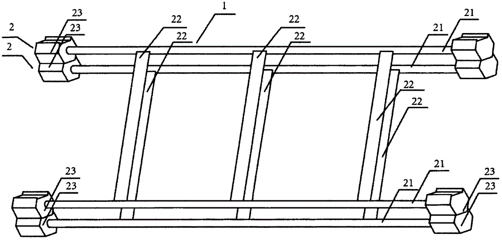
[0046] See attached Figure 5 , a self-lubricating bearing plate sintering plate frame 1, including two layers of plate layer 2;

[0047] The board layer 2 includes three connecting rods 22 and two supporting rods 21; the two ends of the supporting rods 21 are provided with fixing parts 23; 232; the two ends of a connecting rod in the connecting rod 22 are respectively wound in a single circle on the supporting rod in contact with it to form a winding knot 221 and a winding knot 222; the winding knot 221 and the winding knot 222 are connected with the adjacent layer Among the three connecting rods, one connecting rod is located between the fixing parts at both ends of the supporting rod, one connecting rod is located between a fixing part and the end point of the supporting rod close to the fixing part, and one connecting rod is located at the other end. between a fixing member and the end of the support rod adjacent to the fixing member;

[0048] The cross-sectional area of...


PUM

PropertyMeasurementUnit
areaaaaaaaaaaa
areaaaaaaaaaaa
areaaaaaaaaaaa

Abstract

The invention discloses a self-lubricating bearing plate sintering method and a plate containing frame used in the method. The plate containing frame used for sintering of a self-lubricating bearing plate comprises two to six layers of plate containing layers. The plate containing layers comprise supporting rods and connecting rods. The supporting rods are connected through the connecting rods. The two ends of each supporting rod are provided with fixing pieces which are in a regular three-dimensional shape. The fixing pieces are provided with concave surfaces with openings facing upwards or downwards. The fixing pieces of each plate containing layer can be clamped into the concave faces of the fixing pieces of the adjacent plate containing layer in the plate containing frame. According to self-lubricating bearing plates sintered through the plate containing frame, the performances between the layers of plates and between all the parts of the plates of each layer are consistent and are equivalent to the performance of single-layer sintering plates, and defective products do not exist. The problems that the sintering efficiency of the plates is low and sintering quality is not stable in the prior art are successfully solved.

Description

technical field [0001] The invention relates to a metal sintering method, in particular to a self-lubricating bearing plate sintering method and a plate holder used in the method. Background technique [0002] Self-lubricating bearing plates are used in the production and processing of sliding bearings and are based on metal plates sintered with copper alloy powder. Self-lubricating bearing plate has the characteristics of high load capacity, impact resistance, high temperature resistance, strong self-lubricating ability, corrosion resistance, etc. The products made of self-lubricating bearing plate are especially suitable for heavy load, low speed, reciprocating or swinging, etc., which are difficult to lubricate and When forming an oil film, it is mainly used in the production of three types of products: boundary lubrication bearings, oil-free lubrication bearings, and bimetallic bearings. At present, the products have been widely used in construction machinery, automobil...

Claims


Application Information

Patent Timeline
Patent Type & Authority Patents(China)
IPC IPC(8): B22F3/10B22F7/04
Inventor 韩建宋晓静
Owner 江苏立一新材料科技有限公司
Why Eureka
Try Eureka