Differential drive mechanism of internal combustion engine

A technology of differential transmission and internal combustion engine, which is applied in the direction of machines/engines, mechanical equipment, etc. It can solve the problems of cylinder seal design and manufacture difficulty in cylinder processing and manufacturing, insufficient gas pressure, and reduced service life of crankshaft bearings, etc., so as to improve running stability , Improve fuel economy, reduce vibration and noise

Inactive Publication Date: 2016-06-29
宁娟
View PDF7 Cites 0 Cited by
  • Summary
  • Abstract
  • Description
  • Claims
  • Application Information

AI Technical Summary

Problems solved by technology

[0004]1. At the moment of ignition and work, the explosive force of the gas in the cylinder quickly reaches the maximum value. Since the piston is near the top dead center, the bearing position of the crankshaft at this time It bears the largest pressure and frictional resistance, which results in a large loss of mechanical work and reduces the service life of the crankshaft bearing
[0005]2. When the gas explosive force in the cylinder reaches the maximum value, since the piston is near the top dead center, the power output moment arm of the crankshaft connecting rod mechanism is small , the gas pressure in the cylinder cannot be fully converted into work output, thereby significantly reducing the thermal energy-mechanical work conversion efficiency of the internal combustion engine, and affecting the power per liter and fuel consumption performance of the internal combustion engine
[0006]3. The crankshaft connecting rod mechanism is not an axisymmetric part, and the vibration and noise caused by the crankshaft connecting rod mechanism during the operation of the internal combustion engine are large; the crankshaft connecting rod mechanism is difficult to balance, The manufacturing process is complicated and the cost is high; during use, the piston, crankshaft connecting rod mechanism, etc. are easy to wear, and the maintenance cost is high; the limit speed of the internal combustion engine using the crankshaft connecting rod is low, which seriously restricts the improvement of the power-to-weight ratio of the engine
[0007]4. During the operation of an internal combustion engine using a four-stroke crankshaft-connecting rod transmission system, the piston is always in a state of reciprocating motion, and the piston stops at the bottom when intake air When the piston reaches the top dead center, it enters the intake stroke very quickly, so that the cylinder When the volume is the smallest, there is no more time for the exhaust gas to be discharged to the maximum extent. These conditions will eventually affect more fresh mixed oil and gas entering the cylinder, resulting in low engine ventilation efficiency and limiting the increase in engine power.
[0008]5. The combustion time of the mixture in the internal combustion engine cylinder of the crankshaft-connecting rod transmission system is short when the pressure is the highest and the volume is the smallest, and the piston moves downward at this time, making the combustion incomplete , high exhaust gas concentration, low work efficiency
[0009]6. During the operation of the internal combustion engine of the crankshaft-connecting-rod transmission system, the direction of the force exerted by the connecting rod on the piston changes periodically, and when the engine power output is maximum, The force of the connecting rod on the piston also reaches the maximum value along the normal direction of the cylinder wall, which causes a large frictional power loss between the piston and the cylinder, and easily causes damage to the surface between the piston and the cylinder due to friction
For example, insufficient combustion in the cylinder, excessive fuel consumption, too small torque of the output shaft, and difficulty in sealing the cylinder, etc.
Because the expansion pressure of the gas in the triangular rotor engine cylinder acting on the side of the rotor is divided into two forces, one force pushes the output shaft to rotate, while the other force points to the center of the output shaft, resulting in too small output torque of the whole machine; because its cylinder Long and narrow, the combustion rate is too low and the fuel consumption is too high; because of the special shape of the cylinder, it is difficult to manufacture the cylinder and the design and manufacture of the cylinder seal
Many problems in the above-mentioned triangular rotor engine make it difficult to popularize and use it on a large scale
[0011] In order to solve many problems existing in the internal combustion engine of the crankshaft-connecting-rod transmission system, the Chinese patent "Internal-combustion engine with opposed pistons" (publication number: CN1074083C) uses a multi-lobed cam transmission system to replace the crankshaft of the internal-combustion engine of the crankshaft-connecting-rod transmission system Connecting rod transmission system, thus the internal combustion engine adopting the multi-lobed cam transmission system greatly eases the friction between the piston and the cylinder, and has a relatively compact structure, but the patent still has "1. In an instant, the explosive force of the gas in the cylinder quickly reaches the maximum value. Since the piston is near the top dead center, the pressure on the bearing part of the crankshaft is the largest at this time, and the frictional resistance is the largest, so the mechanical work lost is also large, and the crankshaft is reduced at the same time. The service life of the bearing; 2. When the gas explosive force in the cylinder reaches the maximum value, since the piston is near the top dead center, the power output arm of the crankshaft connecting rod mechanism is small at this time, and the gas pressure in the cylinder cannot be fully converted into Work output, thus significantly reducing the thermal energy-mechanical work conversion efficiency of the internal combustion engine, affecting the power per liter and fuel consumption performance of the internal combustion engine

Method used


Image

  • Differential drive mechanism of internal combustion engine
  • Differential drive mechanism of internal combustion engine
  • Differential drive mechanism of internal combustion engine

Examples


Embodiment 1

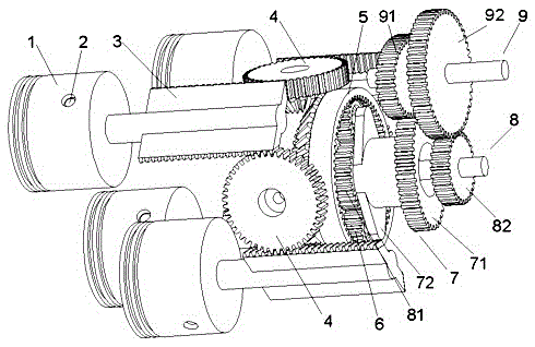
[0075] Example 1: For the first technical solution of the present invention, see Figure 1 to Figure 11 . The differential transmission mechanism of an internal combustion engine includes a piston 1, a piston pin 2, a first rack 3, a first transfer gear shaft 4, a first incomplete gear 5, a first planetary gear 6, a first planetary carrier gear 7, a first A central gear shaft 8 and an output gear shaft 9.

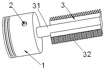
[0076] The internal combustion engine adopts a four-stroke working mode, and has four cylinders of cylinder A, cylinder B, cylinder C and cylinder D in total. The axes of the cylinders are parallel to each other, and the axes of the cylinders are equidistantly distributed in the circumferential direction. During the operation of the internal combustion engine, each cylinder performs the suction, compression, work, and exhaust strokes in a clockwise direction. In each cylinder, the piston pin 2 connects and fixes the first rack 3 to the piston 1, and reciprocates as a wh...

Embodiment 2

[0081] Example 2: For the second technical solution of the present invention, see Figure 12 to Figure 16 , the present embodiment is a differential transmission mechanism that can be applied to an internal combustion engine, and its differential transmission system consists of a piston 1, a piston pin 2, a second rack 3a, a second transfer gear shaft 4a, and a second incomplete gear 5a , the first planetary gear 6, the first planetary carrier gear 7, the first sun gear shaft 8 and the output gear shaft 9.

[0082] The internal combustion engine adopts a four-stroke working mode, and there are four cylinders of cylinder A', cylinder B', cylinder C' and cylinder D'. The axes of the cylinders are parallel to each other, and the axes of the cylinders are distributed in a rectangular array. During the operation of the internal combustion engine, each cylinder is Figure 24 The numbers of cylinder A', cylinder B', cylinder C' and cylinder D' shown in the sequence carry out sucti...

Embodiment 3

[0087] Example 3: The third technical scheme of the present invention, see Figure 17 to Figure 22 . This embodiment is a differential transmission mechanism that can be applied to an internal combustion engine, and its differential transmission system consists of a piston 1, a piston pin 2, a second rack 3a, a second transfer gear shaft 4a, a third incomplete gear 5b, The second planetary gear 6a, the second planetary carrier gear 7a, the second sun gear shaft 8a, and the output gear shaft 9 are composed.

[0088] The internal combustion engine adopts a four-stroke working method and has four cylinders in total, such as Figure 24 As shown, the spatial arrangement of the cylinders, the stroke sequence of the cylinders, the force transmission and motion coordination between the second racks 3a in each cylinder, and the output of the piston work to the third incomplete gear 5b, etc., are related to The same as that of embodiment 2.

[0089] The complete teeth on the third ...


PUM


Abstract

The invention discloses a differential transmission mechanism of an internal combustion engine. A piston is connected to a connecting rod shaft of a first rack through a piston pin, and a spur gear of the first transfer gear shaft meshes with a helical rack of the first rack; and the first The sector gear of the transfer gear shaft meshes with the incomplete bevel teeth of the first incomplete gear; the straight teeth on the inner circumference of the first incomplete gear mesh with the two first planetary gears; the sun gear is installed between the two first planetary gears and meshing, the output gear meshes with the shaft end gear, and the oval gear B meshes with the oval gear A of the first planet carrier gear. The invention can greatly reduce the fuel consumption of the engine, improve the fuel economy and improve the emission of exhaust gas from the engine. It can improve the ventilation efficiency of the engine and the limit speed of the engine, thereby greatly increasing the power-to-weight ratio of the engine; it can improve the running stability of the engine, reduce engine vibration and noise, and prolong the service life of the engine.

Description

technical field [0001] The invention relates to the technical field of transmission systems of internal combustion engines, in particular to differential transmission mechanisms of internal combustion engines. Background technique [0002] The internal combustion engine mainly includes a fuel supply system, an ignition system, a cooling system, a lubrication system, a transmission system, etc. In modern automobiles, shipping and various power equipment, the internal combustion engine of the crankshaft connecting rod transmission system is the most widely used. It has a history of more than 100 years since it was applied in 1898. Its basic working principle has not changed, that is, the piston moves up and down in the cylinder driven by the high-pressure gas burned, and drives the crankshaft to rotate through the connecting rod. The piston from the top dead center to the bottom dead center (or the crankshaft rotates 180 degrees) is called a stroke. A four-stroke internal c...

Claims


Application Information

Patent Timeline
Patent Type & Authority Patents(China)
IPC IPC(8): F02B75/32
Inventor 熊薇唐仁杰
Owner 宁娟
Why Eureka
Try Eureka