Silicon-containing film and method for forming silicon-containing film

A technology containing silicon film and silicon element, applied in the direction of gaseous chemical plating, nanotechnology, coating, etc., can solve the problems of reduced barrier property, peeling and cracking of sealing film, increased film stress, etc., and achieve the effect of stable barrier property

Inactive Publication Date: 2014-11-19
TORAY ENG CO LTD
View PDF7 Cites 3 Cited by
  • Summary
  • Abstract
  • Description
  • Claims
  • Application Information

AI Technical Summary

Problems solved by technology

Therefore, for a sealing film that has good adhesion and has not peeled off immediately after the film is formed, moisture infiltrating into the interior of the solar cell module, and moisture infiltrating into the laminated film of the sealing film causes the sealing film to expand, resulting in increased film stress , peeling and cracks occur in the sealing film, and there is a problem that the barrier property decreases

Method used


Image

  • Silicon-containing film and method for forming silicon-containing film
  • Silicon-containing film and method for forming silicon-containing film
  • Silicon-containing film and method for forming silicon-containing film

Examples


Embodiment 1

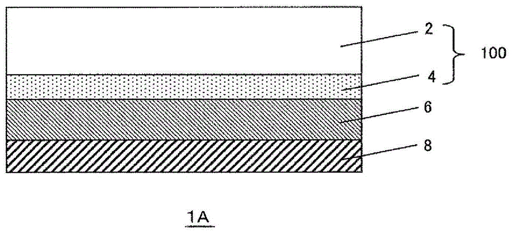
[0091] An Ag layer with a thickness of 200 nm was formed on a part of the surface of the glass substrate. This substrate was placed on a substrate fixing table in the film formation chamber so that the surface having the Ag layer faced the loop antenna side. Then the internal pressure of the film forming chamber is decompressed to 9.9×10 through the exhaust system -5 Below Pa. After the decompression in the film-forming chamber is completed, HMDSO gas is introduced into the film-forming chamber. The introduction rate of the HMDSO gas is 3 sccm to 45 sccm.

[0092] Next, a high-frequency current is passed from the high-frequency power supply to the loop antenna. The plasma power at this time was 1 kW to 10 kW. A surface reaction proceeds on the surface of the substrate to form a base film covered with a plastic film. After 1 minute, the flow control valve was closed to stop the introduction of HMDSO gas.

[0093] After the formation of the base film, a stress relaxation l...

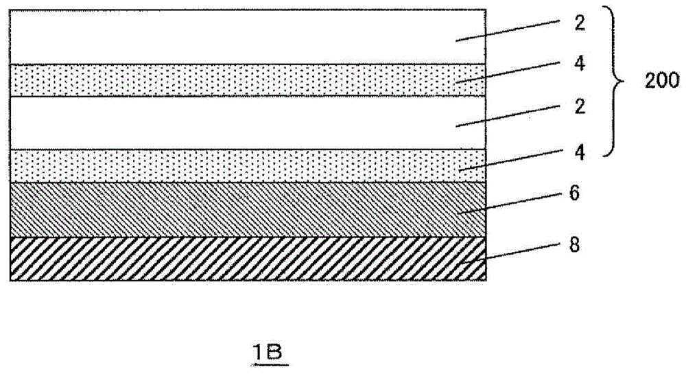
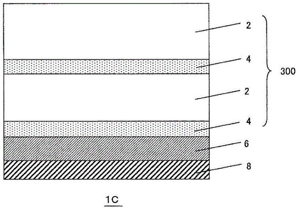
Embodiment 2~5 and comparative example 1~8

[0097] In Example 1, each laminated body was obtained in the same manner as in Example 1, except that the thicknesses of the stress relaxation layer and the barrier layer and the number of layers were changed as shown in Table 2. In Comparative Examples 2 and 5, no barrier layer was provided.

[0098] Peeling evaluation immediately after film production

[0099] The peeling state immediately after film formation of the laminated bodies obtained in Examples 1-5 and Comparative Examples 1-8 was visually observed. The results were evaluated according to the following criteria. The results are shown in Table 2.

[0100] ○: No peeling or peeling of the silicon-containing film was observed

[0101] ×: Peeling and peeling of the silicon-containing film were observed

[0102] In the results of the above test, peeling and peeling of the silicon-containing film were observed in the laminates of Comparative Examples 1 and 4. Peeling and peeling of the silicon-containing film were no...


PUM

PropertyMeasurementUnit
thicknessaaaaaaaaaa
thicknessaaaaaaaaaa
thicknessaaaaaaaaaa

Abstract

The purpose of the present invention is to provide a film that will not peel as a result of changes over time and has stable barrier properties due to a sealed film structure with low stress and low water absorption. Specifically, provided is a silicon-containing film that is provided with the following: a first chemical vapor deposition layer, formed by a plasma chemical vapor deposition (CVD) method, that comprises elemental silicon and has an oxygen concentration of at least 0% and less than 10% by element; and a second chemical vapor deposition layer, formed by a plasma CVD method, that comprises elemental silicon and has an oxygen concentration of greater than 35% and no more than 70% by element. The ratio (L2 / L1) of the thickness (L1) of the first chemical vapor deposition layer and the thickness (L2) of the second chemical vapor deposition layer is 1.5-9.

Description

technical field [0001] The present invention relates to a silicon-containing film and a method for forming a silicon-containing film. Background technique [0002] In recent years, in thin-film devices such as thin-film solar cell modules, there is a need for a sealing film that prevents moisture from entering the device, does not peel off over time, and has stable barrier properties. A thin-film solar cell module is constructed by sequentially laminating a transparent electrode film, a functional film (power generation layer), and an electrode film on a substrate. In order to maintain stable power generation efficiency in this thin-film solar cell module, for example, prevention of moisture intrusion into the solar cell is mentioned. That is, solar battery cells have a property of being corroded and degraded when exposed to water, and deterioration of solar battery cells leads to a decrease in power generation efficiency. Therefore, in a solar cell, a sealing layer made o...

Claims


Application Information

Patent Timeline
Patent Type & Authority Applications(China)
IPC IPC(8): C23C16/40C23C16/02H01L51/44H01L51/52H05B33/04
CPCY02E10/52H01L51/424H01L51/5253H01L31/048H01L51/0078H01L51/0046H01L31/03926H01L51/448B82Y10/00C23C16/0272C23C16/401H01L2251/308H01L31/0481Y02E10/549H01L21/0245H01L21/02532H01L21/0262Y02E10/547H10K85/211H10K85/311H10K30/20H10K30/88H10K50/844H10K2102/103H01L31/0224H01L31/022475H01L31/022483H01L31/028H01L31/1804
Inventor 山下雅充藤元高佳岩出卓
Owner TORAY ENG CO LTD
Why Eureka
Try Eureka