


Quick Research
Generate reliable direction feasibility study reports for your R&D in just a few steps.

Technical Q&A
Discover and master advanced knowledge NOW. Basics, ideas, possibilities, all at once.

Find Solutions
As an expert in R&D theories, this can generate solutions to your technical problems instantly.

Evaluate Feasibility
Analyze your overall solution with one click, know your potential R&D risks in advance.

Monitor Landscape
Get weekly tech updates, stay abreast of the latest tech innovations and key insights.
Solenoid drive type angular vibration table
A technology of angular vibrating table and electromagnetic drive, which is applied in the direction of instruments, etc., can solve the problems of large output waveform distortion, achieve the effect of no friction friction, simplify winding process, and reliable operation
- Summary
- Abstract
- Description
- Claims
- Application Information
AI Technical Summary
Problems solved by technology
Method used
Image

Examples
Embodiment 1
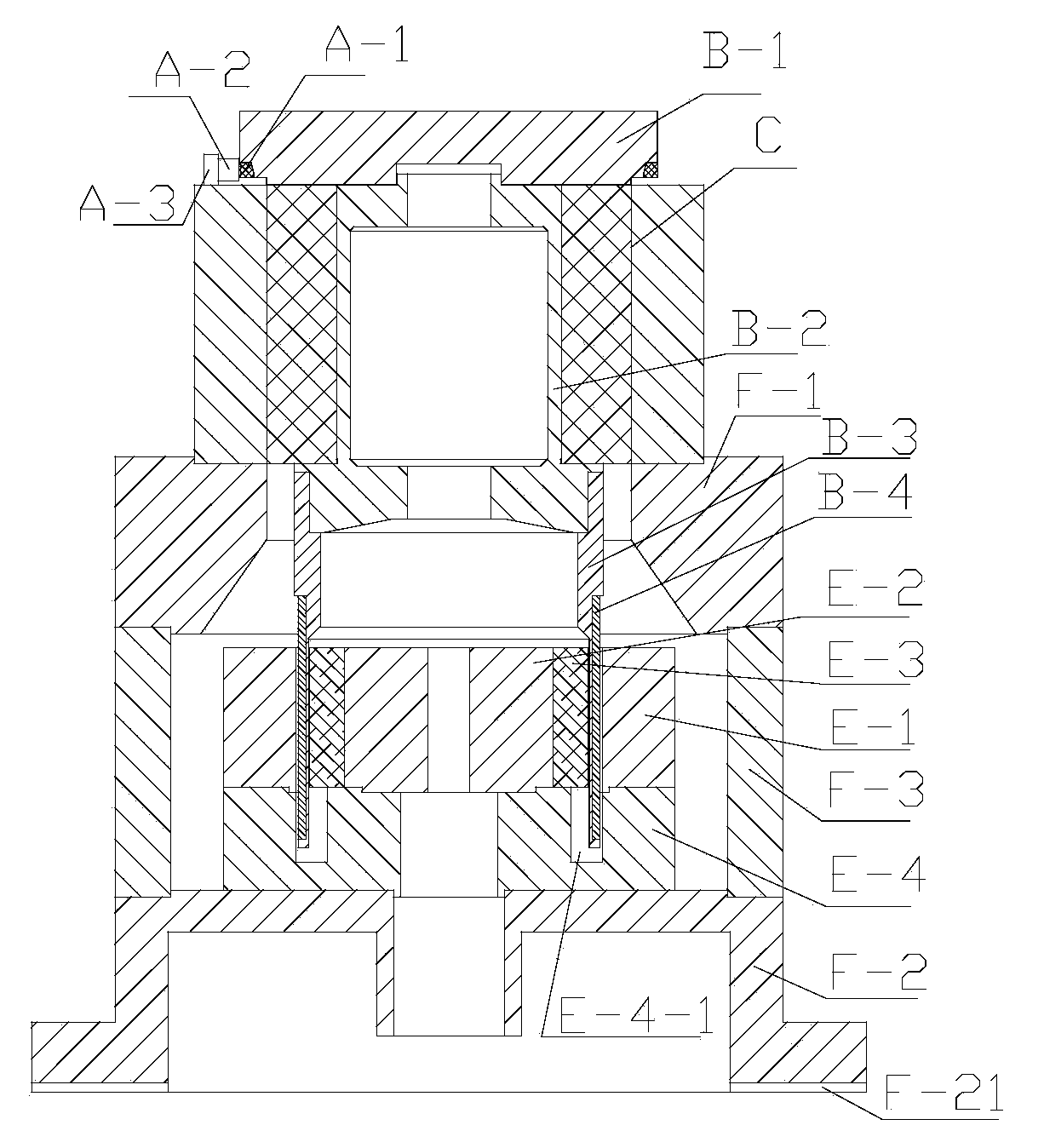
[0043] Such as figure 1 As shown, an electromagnetically driven angular vibrating table includes a shell, a worktable B-1, a spindle B-2 that drives the worktable B-1 to rotate, a moving coil assembly, a magnetic circuit assembly, an electroviscoelastic feedback control assembly, an air Bearings and angular displacement sensors;
[0044] The main shaft B-2 is fixedly connected with the moving coil assembly, and the moving coil assembly includes the moving coil base B-3 connected with the main shaft B-2 and the coil B-4 wound on the moving coil base B-3, and the moving coil base B-3 Fixed connection with main shaft B-2;
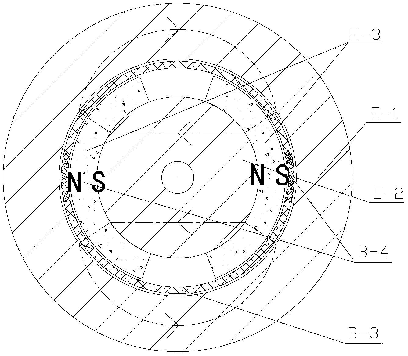
[0045] Such as figure 2 As shown, the magnetic circuit assembly includes the magnetic ring E-1, the central magnetic pole E-2 and the magnetic steel E-3, and is formed by the magnetic conductive ring E-1, the central magnetic pole E-2, the magnetic steel E-3 and the air gap. Closed magnetic circuit; the central magnetic pole E-2 is located in the magnetic ...
Embodiment 2
[0055] The difference between this embodiment and the first embodiment lies in the specific structure of the air bearing, and the structure of other components except the air bearing is the same as that of the first embodiment.
[0056] Specifically: if Figure 4 As shown, the air bearing includes bearing seat C-1 and bearing body C-2, the main shaft B-2 is socketed in the bearing body C-2, the bearing body C-2 is socketed in the bearing seat C-1, and the bearing seat C -1 is fixed with the bearing body C-2, and the bottom of the main shaft B-2 is provided with a step matching with the bearing body C-2;
[0057] The outer surface of the bearing body C-2 is provided with a circular air intake groove C-21, and the bearing seat C-1 is provided with an air intake hole C-11 communicating with the air intake groove C-21, and the bearing body C -2 is provided with the radial air guide hole between the bearing body C-2 and the main shaft B-2, which guides the gas to the upper axial a...
Embodiment 3
[0068] The difference between this embodiment and Embodiment 1 lies in the coil of the moving coil assembly, and the structure of other components except the coil is the same as that of Embodiment 1.
[0069] Such as Figure 5 As shown, the coil B-4 of the moving coil assembly covers the outer surface of the moving coil base B-3. Such as Image 6 As shown, the coil includes a coil winding B-4-1 and an insulating layer B-4-3, the coil winding B-4-1 and the insulating layer B-4-3 are arranged at intervals, and the coil winding B-4-1 has at least one layer , the insulating layer B-4-3 is made of epoxy resin glue and glass cloth, and the insulating layer completely covers the coil winding B-4-1 inside. Such as Figure 7 As shown, the coil winding includes the first coil B-4-1-1 and the second coil B-4-1-2, the first coil B-4-1-1 is wound counterclockwise from inside to outside, the second coil B -4-1-2 Winding clockwise from outside to inside, the first coil B-4-1-1 and the seco...
PUM
 Abstract
Description
Claims
Application Information
 - R&D Engineer
- R&D Manager
- IP Professional
- Industry Leading Data Capabilities
- Powerful AI technology
- Patent DNA Extraction
Browse by: Latest US Patents, China's latest patents, Technical Efficacy Thesaurus, Application Domain, Technology Topic, Popular Technical Reports.
© 2024 PatSnap. All rights reserved.Legal|Privacy policy|Modern Slavery Act Transparency Statement|Sitemap|About US| Contact US: help@patsnap.com