
Indoor air purification device

A technology for purifying devices and indoor air, applied in air conditioning systems, space heating and ventilation, chemical instruments and methods, etc. problems, to achieve the effect of eliminating secondary pollution, small footprint and simple structure

Active Publication Date: 2014-12-10
CHINA AGRI UNIV
View PDF6 Cites 14 Cited by
  • Summary
  • Abstract
  • Description
  • Claims
  • Application Information

AI Technical Summary

Problems solved by technology

The low-temperature plasma method can completely decompose organic matter, and has the function of high-voltage electrostatic dust removal, but ozone still remains in the treated air
3. Activated carbon adsorption method: Activated carbon is an important adsorbent for removing polluted gases by physical methods. Pollutants play a role in transfer, and the polluted gas is not really oxidized and decomposed; and the filter element needs to be cleaned and replaced regularly, so this method cannot really remove the pollutants in the air
However, since the photocatalytic reaction is a surface reaction, whether the pollutants can fully contact the surface of the catalyst will directly affect the efficiency of the air purifier.
[0004] It can be seen that due to the limitations of the above-mentioned technology itself, the purpose of efficiently removing pollutants in the air cannot be achieved, and it may even cause secondary pollution

Method used


Image

  • Indoor air purification device
  • Indoor air purification device
  • Indoor air purification device

Examples


Embodiment Construction

[0016] The present invention will be described in detail below in conjunction with the accompanying drawings and embodiments.

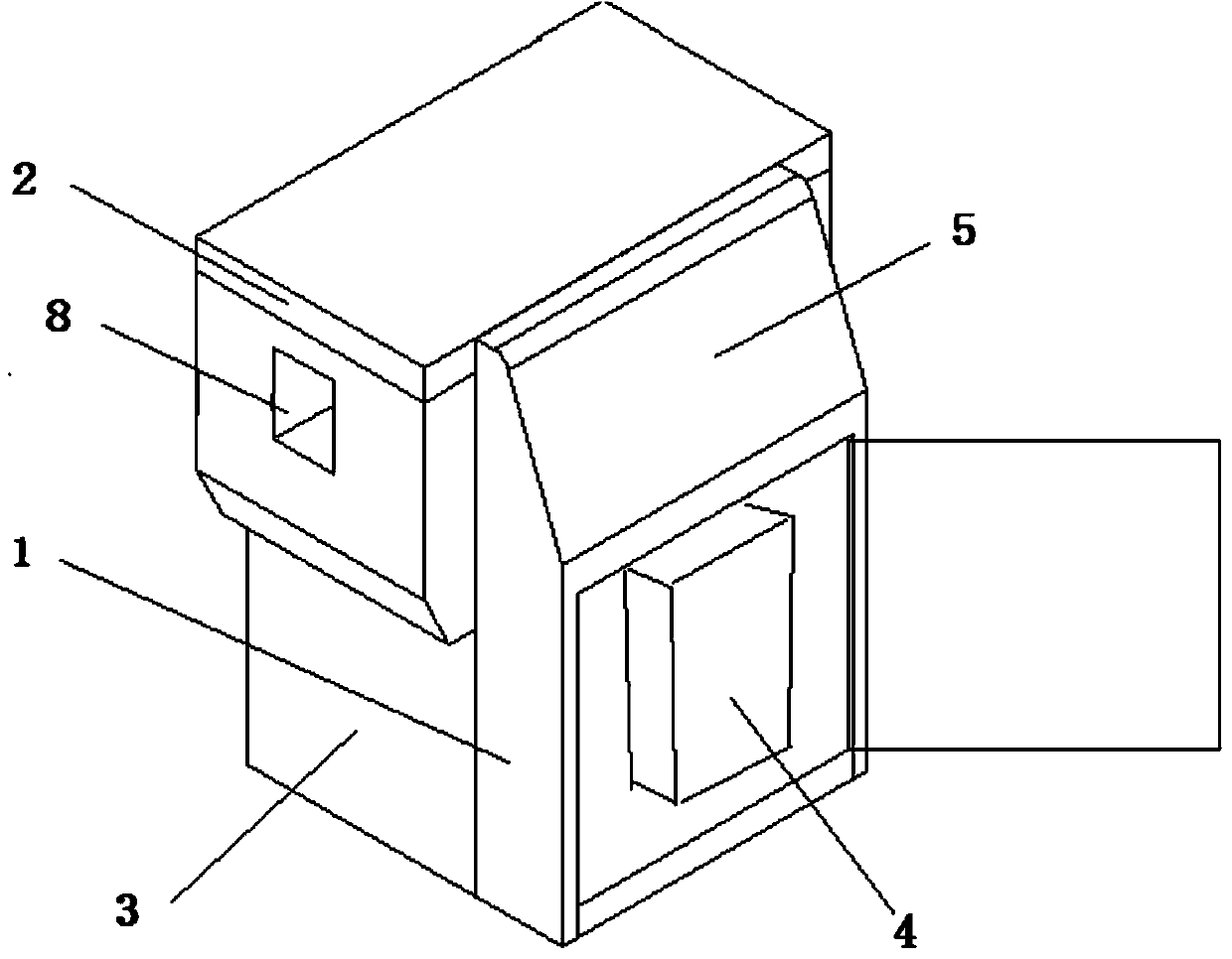
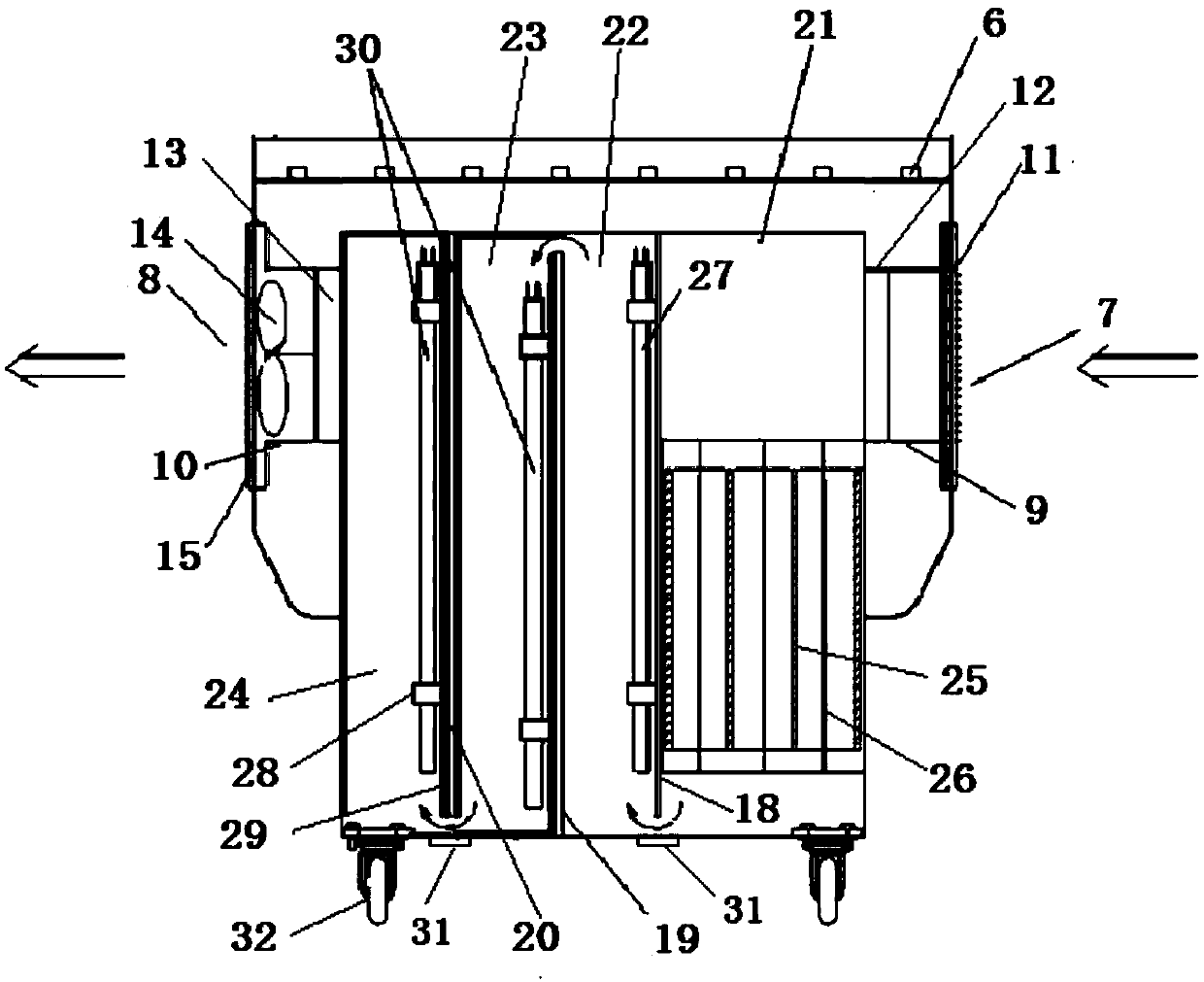
[0017] like figure 1 , figure 2 As shown, the present invention includes a front electrical box 1 , an upper electrical box 2 and a reactor 3 .

[0018] The front electrical box 1 of the present invention is provided with a low-temperature plasma high-voltage high-frequency power supply 4 , and a control panel 5 is provided on the upper surface of the front electrical box 1 .

[0019] Several (e.g., eight, but not limited to) ultraviolet lamp ballasts 6 are provided at intervals on the top of the upper electrical box 2 of the present invention, and an air inlet 7 and an air outlet 8 are arranged on both sides of the lower part, and the air inlet 7 is provided An air intake device 9 is provided, and an air outlet device 10 is arranged at the air outlet 8 . An air filter 11 and a flow stabilization device 12 are sequentially arranged in the air inta...


PUM


Abstract

The invention relates to an indoor air purification device. The indoor air purification device is characterized by comprising a front electrical box, an upper electrical box and a reactor, a low-temperature plasma high-voltage high-frequency power source is arranged in the front electrical box, a control panel is arranged on the surface of the upper portion of the front electrical box, a plurality of ultraviolet lamp ballasts are arranged on the top inside the upper electrical box at intervals, an air inlet and an air inlet device are arranged on one side of the lower portion of the upper electrical box, and an air outlet and an air outlet device are arranged on the other side; an air filtering net and a flow stabilizer are arranged in the air inlet device in sequence, a flow stabilizer, an axial flow fan and a fan housing are sequentially arranged in the air outlet device, three separating plates are arranged inside the reactor at intervals and divide the reactor into four reaction chambers, including a low-temperature plasma reaction chamber, a UVC dual-wave optical catalytic oxidation chamber, a first nanometer Au / TiO2 photodegradation chamber and a second nanometer Au / TiO2 photodegradation chamber, and the four reaction chambers are arranged in a serial-connection mode from front to back. The indoor air purification device can fully decompose pollution air, effectively avoid secondary pollution and be widely applied to the technical field of air purification.

Description

technical field [0001] The invention relates to an air purification device, in particular to an indoor air purification device. Background technique [0002] With the rapid development of modern industry and agriculture, the corresponding pollutants are also increasing. People's demand for life is increasing day by day, especially for the pollutants in the closed space where people and animals live, such as formaldehyde, benzene, ammonia, hydrogen sulfide, smoke and so on. [0003] At present, the methods used to remove these pollutions mainly contain the following: 1. Ozone method: This method utilizes the strong oxidative property of ozone to decompose the polluted gases in the air. Although the method has the effect of purifying the air to a certain extent, the excessive Ozone will cause secondary pollution. In addition, the method of using ultraviolet rays to generate ozone can easily cause ultraviolet rays to leak, thereby causing harm to humans or animals. 2. Low-te...

Claims


Application Information

Patent Timeline
Patent Type & Authority Applications(China)
IPC IPC(8): F24F1/02F24F11/02B01D46/10B01D53/75
Inventor 施正香赵芙蓉李保明陈刚
Owner CHINA AGRI UNIV
Learn More