Treatment method for liquid sulfur degassing in sulfur recovery process

A technology for liquid sulfur degassing and sulfur recovery, which is used in sulfur preparation/purification, chemical industry, climate sustainability, etc., and can solve problems such as substandard discharge and unsatisfactory sulfur liquid sulfur degassing.

Active Publication Date: 2014-12-31
CHINA PETROLEUM & CHEM CORP
View PDF5 Cites 8 Cited by
  • Summary
  • Abstract
  • Description
  • Claims
  • Application Information

AI Technical Summary

Problems solved by technology

[0007] In order to solve the above-mentioned technical problems, the present invention proposes a process with low investment and low operating cost to reduce the sulfur recovery unit flue gas SO 2 Emission concentration, to solve the technical problems of unsatisfactory liquid sulfur degassing and substandard discharge in the existing sulfur recovery

Method used


Image

  • Treatment method for liquid sulfur degassing in sulfur recovery process
  • Treatment method for liquid sulfur degassing in sulfur recovery process
  • Treatment method for liquid sulfur degassing in sulfur recovery process

Examples


Embodiment 1

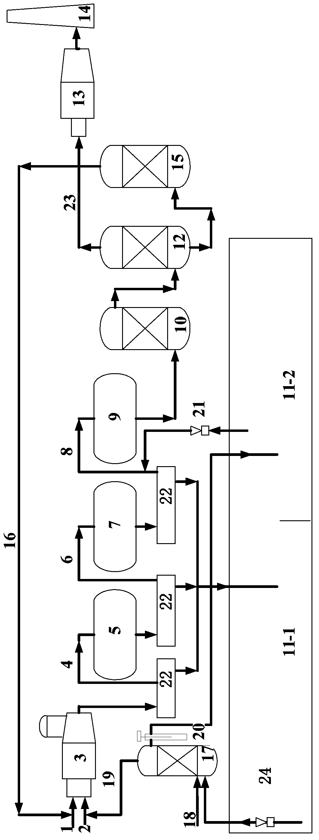
[0046] process such as figure 1 As shown, it includes thermal reaction stage, catalytic reaction stage, tail gas purification treatment stage and liquid sulfur degassing treatment stage.

[0047] 1) Thermal reaction stage:

[0048] Contains H 2 S: 30-100 (v / v)% acid gas (1) and air (2) are partially combusted into SO in the sulfur furnace (3) 2 , in the sulfur furnace (3) at high temperature (900-1400°C) H 2 S and SO 2 A Claus reaction occurs to generate elemental sulfur and sulfur-making furnace tail gas (4), the elemental sulfur condenses and enters the undegassed compartment (11-1) of the liquid sulfur pool (11) to recover liquid sulfur, and the sulfur-making furnace tail gas (4) enters catalytic reaction stage. The volume content of sulfur-containing compounds in the tail gas (4) of the sulfur making furnace is: H 2 S: 1-8%, SO 2 : 0.5-4%, organic sulfur: 0-2%.

[0049] 2) Catalytic reaction stage:

[0050] The tail gas (4) of the sulfur making furnace enters the ...

Embodiment 2

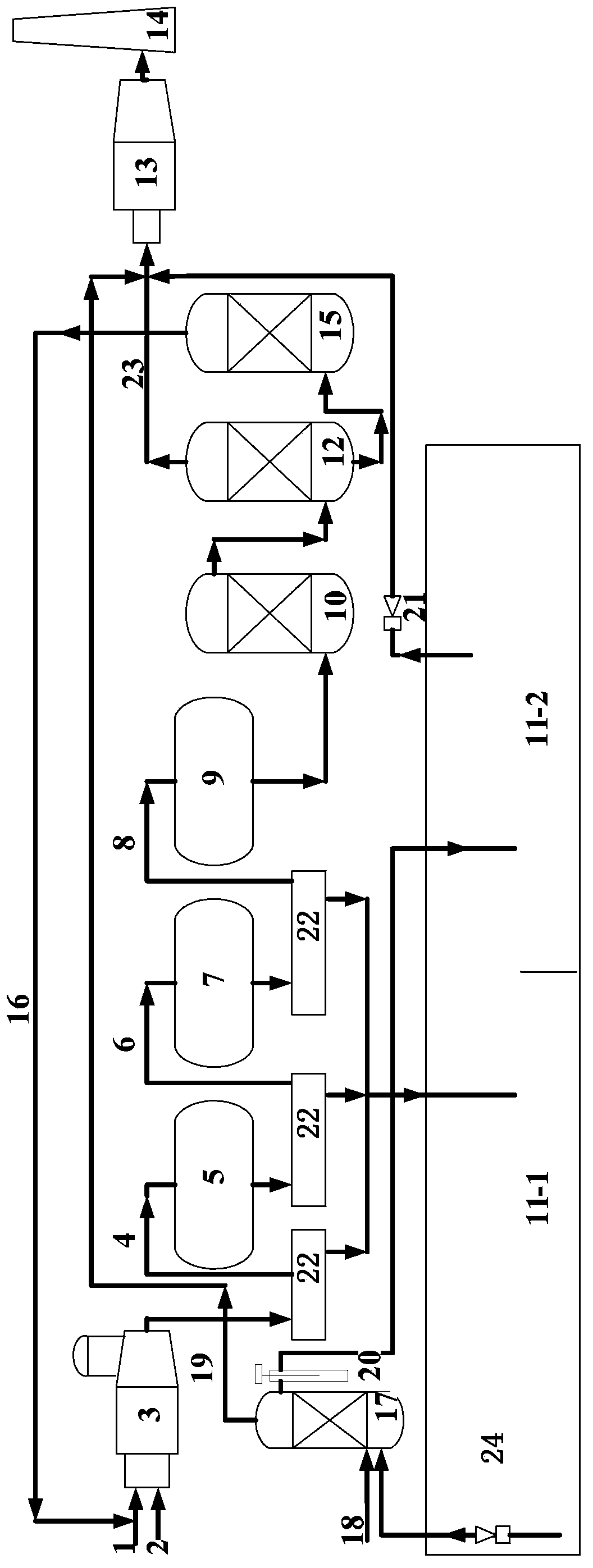
[0058] Except following difference, other is with embodiment 1.

[0059] process such as figure 2 shown.

[0060] The degassed waste gas (19) produced by the liquid sulfur degassing tower (17) and the sulfur-containing waste gas extracted by the steam extractor (21) are all introduced into the incinerator (13) to be incinerated and converted into SO 2 After being discharged through the chimney, the flue gas SO 2 Emission concentration 400-960mg / m 3 between. Hydrogen sulfide content in liquid sulfur and flue gas SO 2 The emission concentration is shown in Table 1.

Embodiment 3

[0062] Except following difference, other is with embodiment 1.

[0063]Close the liquid sulfur degassing tower (17), and only rely on the steam extractor (21) to extract the sulfur-containing waste gas volatilized at the top of the liquid sulfur tank, and then introduce the sulfur-containing waste gas into the hydrogenation reactor (9) for processing. Hydrogen sulfide content in liquid sulfur and flue gas SO 2 The emission concentration is shown in Table 1.


PUM


Abstract

Belonging to the technical field of sulfur recovery, the invention specifically relates to a treatment method for liquid sulfur degassing. The method includes a liquid sulfur degassing treatment stage: pressurizing undegassed liquid sulfur collected in an undegassed compartment of a liquid sulfur pool, then subjecting the pressurized undegassed liquid sulfur and compressed air to catalytic reaction together, removing H2S dissolved in liquid sulfur, mixing the degassed exhaust gas with air, then leading the mixture into a sulfur production furnace, returning the mixture to the thermal reaction stage again for further recovery of elemental sulfur; and recovery and storage of degassed liquid sulfur. The treatment method for liquid sulfur degassing provided by the invention is efficient, energy-saving and economical, and can greatly lower the SO2 emission concentration and H2S content.

Description

technical field [0001] The invention belongs to the technical field of sulfur recovery, and in particular relates to a treatment method for degassing liquid sulfur in a sulfur recovery process. Background technique [0002] With the development of society, the problem of environmental pollution has become a restrictive factor for the rapid economic development. Industrially developed countries have very strict requirements on sulfur emissions. The United States Federal Government Environmental Protection Agency regulations stipulate that industrial heating furnace flue gas, sulfur tail gas and catalytic cracking regeneration flue gas SO 2 The emission concentration limit is 50ppm (v), equivalent to about 143mg / m 3 . Foreign countries have been studying the new technology of Claus method sulfur recovery tail gas treatment. In 2007, the United States published a process patent (US7311891B2) for recovering sulfur from Claus tail gas by adsorption method, which will contain S...

Claims


Application Information

Patent Timeline
IPC IPC(8): C01B17/04
CPCY02P20/10
Inventor 刘爱华王建华许金山刘剑利张义玲刘增让陶卫东
Owner CHINA PETROLEUM & CHEM CORP
Why Eureka
Try Eureka