Underground water pollution restoration system and construction method thereof

A groundwater and in-situ remediation technology, applied in the treatment of polluted groundwater/leachate, chemical instruments and methods, biological water/sewage treatment, etc. fouling and other issues

Active Publication Date: 2015-01-07
SHANGHAI MUNICIPAL ENG DESIGN INST GRP
View PDF5 Cites 30 Cited by
  • Summary
  • Abstract
  • Description
  • Claims
  • Application Information

AI Technical Summary

Problems solved by technology

[0004] Although the conventional continuous reaction wall has little interference to the groundwater flow field, is simple in structure, and is easy to design and construct, it has the following disadvantages: (1) It is only suitable for the case where the aquifer is buried shallowly and the pollutant plume is small. If the aquifer thickness or If the polluted area is relatively large, the area of ​​the continuous reaction wall will be large, and the project cost will increase significantly; (2) The groundwater flow field in the actual polluted site is complex, and there may be multi-directional dominant flows, and as the reaction of the reaction wall proceeds, Precipitation of reaction products leads to a decrease in porosity and permeability coefficient, and there may be scaling and silting in the reaction wall, and pollutants may leak from both sides of the reaction wall with the water flow
(3) When the groundwater pollution components are complex and diverse, the single-layer reaction grid will not be able to deal with multi-polluting components
The above shortcomings greatly limit the in-situ engineering application of the continuous reaction wall

Method used


Image

  • Underground water pollution restoration system and construction method thereof
  • Underground water pollution restoration system and construction method thereof

Examples


Embodiment Construction

[0018] The features of the present invention and other related features will be further described in detail below with examples in conjunction with the accompanying drawings, so as to facilitate the understanding of those skilled in the art.

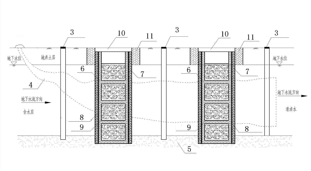
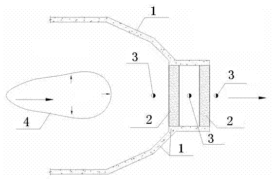
[0019] An in-situ repair system for groundwater of the present invention is composed of three major parts: a vertical anti-seepage wall 1 , a multi-processing unit reaction grid 2 , and a groundwater monitoring well 3 . The bottom of the vertical anti-seepage wall 1 needs to enter the water-resisting layer 5 for 1~2m, and the structure of the vertical anti-seepage wall 1 is generally a plastic concrete wall, cement mixing pile, concrete-bentonite and other structural forms. The vertical anti-seepage wall 1 is a semi-closed structure, and the opening is airtightly connected with both ends of the reaction grid 2 of the multi-processing unit to form a series funnel-water gate system of the reaction grid 2 of the multi-processing unit. The m...


PUM


Abstract

The invention relates to an underground water in-situ restoration system which is characterized by comprising a vertical impermeable wall arranged along the periphery of the polluted zone, wherein the vertical impermeable wall is in a semi-closed structure; the opening of the vertical impermeable wall is provided with a multi-treatment-unit reaction grid; the multi-treatment-unit reaction grid is arranged on the front edge downstream the underground water pollution stream and is perpendicular to the underground water flow; and the upstream and downstream of the multi-treatment-unit reaction grid are respectively provided with an underground water monitoring well for determining the change conditions of water level and water quality before and after underground water restoration. The system can overcome the defects of narrow restoration range, high clogging tendency, single treated pollution component and the like of the traditional continuous reaction wall in engineering application, can effectively restore underground water pollution streams with multiple pollutant components and complicated underground flow field, and can monitor the dynamic changes of water level and water quality of underground water in real time, thereby periodically cleaning and replacing the reaction medium in the treatment unit reaction grid.

Description

technical field [0001] The invention belongs to the field of groundwater pollution restoration and prevention in polluted sites, and in particular relates to a groundwater pollution restoration system and a construction method thereof. Background technique [0002] With the development of human industry, groundwater pollution is becoming more and more serious. In most cities in my country, the groundwater is polluted to varying degrees by organic and inorganic toxic and harmful pollutants, and it has shown a trend of being somewhat face-to-face, from shallow to deep, from urban to rural areas, and the degree of pollution is becoming increasingly serious. According to the continuous monitoring and statistics of 118 cities for 2 to 7 years by relevant departments, about 64% and 33% of the urban groundwater have suffered from severe and light pollution, and only 3% of the urban groundwater is basically clean. Especially in the polluted sites left by urban industrial relocation...

Claims


Application Information

Patent Timeline
Patent Type & Authority Applications(China)
IPC IPC(8): C02F1/28C02F1/52C02F1/72C02F1/70C02F3/00C02F1/42C02F9/00
CPCC02F1/28C02F1/42C02F1/52C02F1/70C02F1/72C02F3/00C02F9/00C02F2103/06
Inventor 王艳明罗小勇陈思曹泳民王华金
Owner SHANGHAI MUNICIPAL ENG DESIGN INST GRP
Why Eureka
Try Eureka