Passive channel correction method and system of rotary array of outer transmitter-based radar

A technology for external radiation source radar and channel correction, which is applied in the field of passive channel correction of external radiation source radar rotating arrays, and can solve problems such as system errors, troublesome placement and maintenance of auxiliary signal sources, and complex near-field electromagnetic environment of array antennas.

Active Publication Date: 2015-01-07
WUHAN UNIV
View PDF5 Cites 17 Cited by
  • Summary
  • Abstract
  • Description
  • Claims
  • Application Information

AI Technical Summary

Problems solved by technology

The active correction method also includes far-field correction and near-field correction. In the far-field correction, the auxiliary signal source is placed in an open field far enough in front of the antenna to transmit the correction signal, and then the output of each receiving channel is measured, and the spatial position of the array is deducted. The phase difference of the array error information is obtained. The placement and maintenance of the auxiliary signal source in this correction method is a troublesome thing, and it is difficult to achieve real-time correction. In addition, when the orientation information of the auxiliary signal source deviates, it will bring systematic errors to the correction.
In contrast, near-field correction places the auxiliary signal source near the antenna array, making the placement and maintenance of the auxiliary signal source relatively easy, and can achieve real-time correction. However, the near-field electromagnetic environment of the array antenna is complex, and the correction signal echo is not a theory. The spherical wave on , so that the spatial phase difference that should be deducted cannot be calculated according to the simple geometric relationship, resulting in low measurement accuracy of this method
[0004] In the passive correction method, the channel mismatch coefficient is estimated directly by using the received measured data and some prior information (such as the angle of array rotation) without an auxiliary signal source whose orientation is known accurately, and then continues to compensate and correct. At present, it is proposed at home and abroad A variety of effective methods have been proposed, such as Wylie M P, Roy S, Messer H's literature Joint DOA estimation and phase calibration of linear equispaced (LES) arrays[J].IEEE Transactions on Signal Processing,1994,42(12):3449- 3459, it is proposed to use the Toeplitz characteristic of the uniform linear array receiving signal covariance matrix to solve the array error, but the solution is ambiguous, and corresponding constraints must be added; Weiss A J, Friedlander B.'s literature Eigenstructure methods for direction finding with sensor gain and phase uncertainties [J].Circuits Systems Signal Process,1990,9(3):271-300, proposed to use the orthogonality between the noise subspace and the signal subspace to construct a cost function, and obtain the corrected signal source orientation and array error through iterative operations , but for a uniform linear array, the solution of this method is also ambiguous; the literature of Rockah Y, Messer H, Schultheiss P M. proposes to use multiple unknown azimuth echo signals that do not overlap in time or frequency spectrum, through the maximum likelihood Estimate array error, but requires array to be non-linear
Due to the Vandermont nature of the steering vector of the uniform linear array, the above passive correction method is applied to the uniform linear array widely used in external radiation source radar due to its simple structure and signal processing.

Method used


Image

  • Passive channel correction method and system of rotary array of outer transmitter-based radar
  • Passive channel correction method and system of rotary array of outer transmitter-based radar
  • Passive channel correction method and system of rotary array of outer transmitter-based radar

Examples


Embodiment Construction

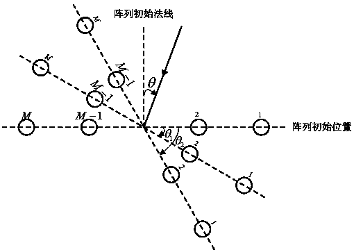
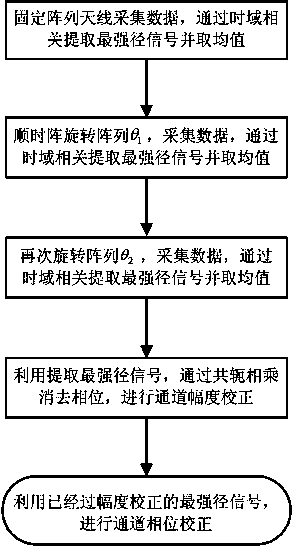
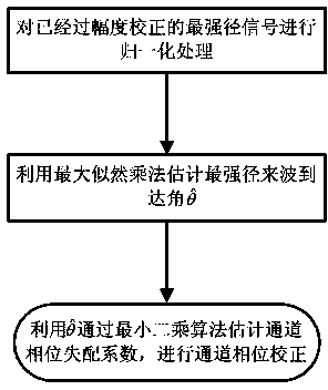
[0064] The key of the present invention is that by rotating the array to receive multi-path echo signals, the problem of channel correction is transformed into the problem of parameter estimation, and thus a relatively accurate estimation of channel mismatch is obtained. Including rotating the array antenna twice or more, and separating the strongest path signal of each rotation through time-domain correlation calculation; using the strongest path signal to estimate the channel amplitude mismatch coefficient to achieve amplitude correction; The corrected strongest path signal and the angle information of the array rotation estimate the channel phase mismatch coefficient to realize phase correction.

[0065] The technical solutions of the present invention will be further specifically described below through embodiments and in conjunction with the accompanying drawings.

[0066] The embodiment establishes the signal model as follows:

[0067] China Mobile Multimedia Broadcasti...


PUM


Abstract

The invention discloses a passive channel correction method and system of a rotary array of an outer transmitter-based radar. An array antenna is rotated two or more times, the strongest path signal of every rotation is separated out through time domain correlation operation, a channel amplitude mismatching coefficient is estimated by the utilization of the strongest path signals with the high signal to noise ratio, and amplitude correction is achieved; a channel phase mismatching coefficient is estimated by the utilization of the strongest path signals with the corrected amplitude and the rotation angle information of the array antenna, and phase correction is achieved. Any auxiliary signal source is not needed any more, and the passive channel correction method and system are the real passive channel correction technical scheme. The passive channel correction method and system have the advantages that echo interference, the multipath effect and other problematic issues involved in an active channel correction method do not exist; by the utilization of the strongest path signal of every array rotation, good precision and robustness are achieved, and operation is easy; the application flexibility of the radar is improved greatly, and while the detection performance is improved, the development cost and maintenance expense of the radar are lowered largely.

Description

technical field [0001] The invention relates to the technical field of array correction, in particular to a passive channel correction method and system for a rotating array of external radiation source radar. Background technique [0002] In recent years, the radar detection technology of external radiation sources using radio, television, satellite and other civil radiation sources has attracted more and more attention. The external radiation source radar system itself does not need to transmit signals, and directly uses the existing electromagnetic wave signals in the environment or the target itself to detect and locate targets. "Four resistance" potential. Some key technologies of external radiation source radar have always been a research hotspot in the radar field. The researches of scholars at home and abroad mainly focus on: multipath clutter suppression, target detection, target tracking, imaging and optimal station layout, etc. However, there are few researches o...

Claims


Application Information

Patent Timeline
Patent Type & Authority Applications(China)
IPC IPC(8): G01S7/40
CPCG01S7/40
Inventor 万显荣方高方亮程丰
Owner WUHAN UNIV
Why Eureka
Try Eureka